Power transmission mechanism

a technology of transmission mechanism and drive wheel, which is applied in the direction of gearing, mechanical control devices, instruments, etc., can solve the problems of increasing the manufacturing cost of the vehicle, difficult to secure a space for installing the mechanism in the vehicle, and the torque required to drive the drive wheels is relatively larg

Inactive Publication Date: 2002-04-11
HONDA MOTOR CO LTD
View PDF9 Cites 100 Cited by
  • Summary
  • Abstract
  • Description
  • Claims
  • Application Information

AI Technical Summary

Problems solved by technology

In addition thereto, if a starter motor for starting the engine is separately provided, still another electric motor is necessitated, which leads to increased manufacturing costs of the vehicle and makes it difficult to secure a space for installing the mechanism in the vehicle.
Further, since the motor for driving the ...

Method used


Image

  • Power transmission mechanism
  • Power transmission mechanism
  • Power transmission mechanism

Examples


Embodiment Construction

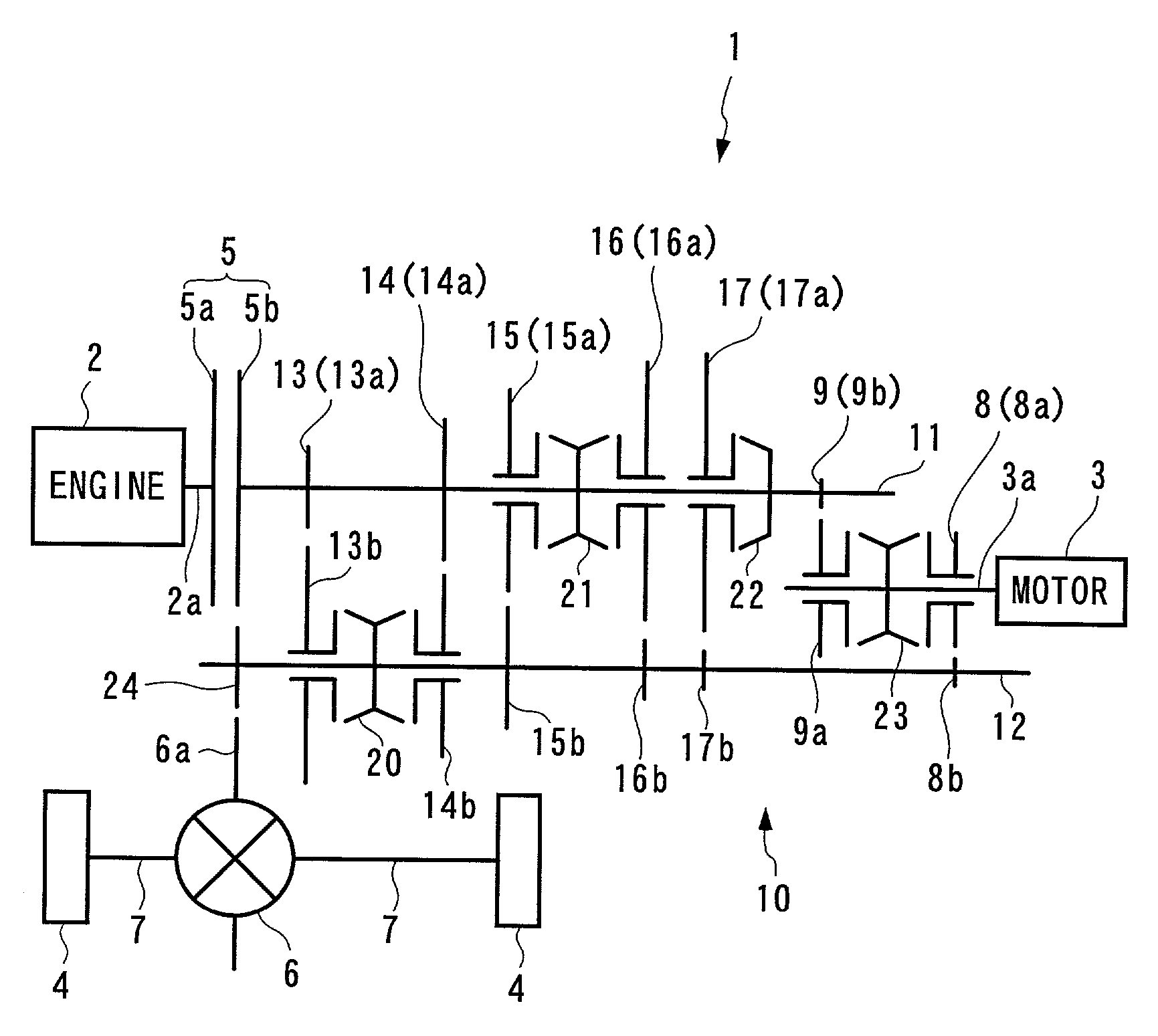
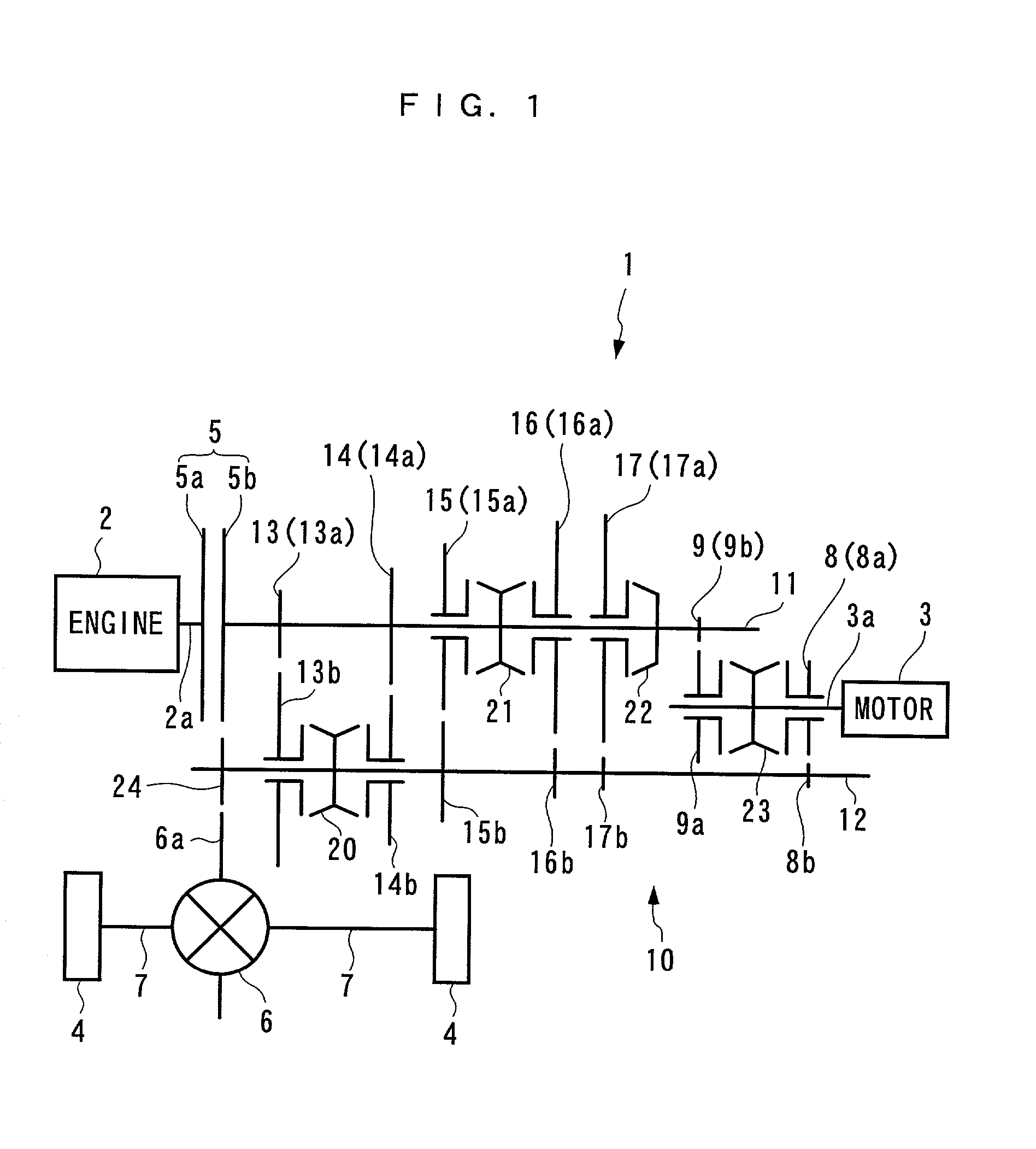
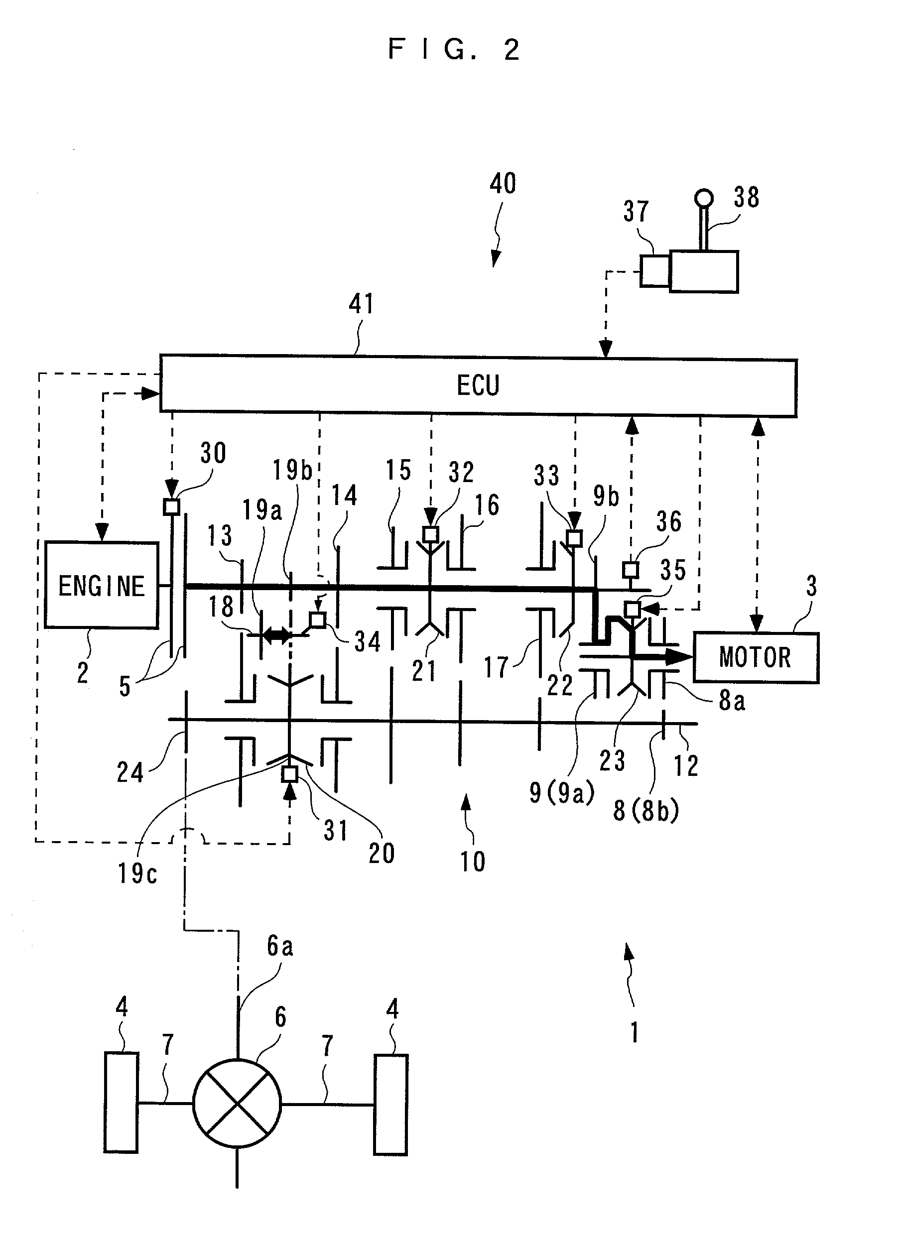
[0032] The invention will now be described in detail with reference to the drawings showing a power transmission mechanism according to an embodiment thereof. FIG. 1 schematically shows the arrangement of a hybrid vehicle to which is applied the power transmission mechanism according to the present embodiment. FIG. 2 schematically shows the arrangement of a control system for controlling the power transmission mechanism, with devices and parts added to the FIG. 1 power transmission mechanism. The power transmission mechanism 1 is capable of selectively connecting an engine 2 and an electric motor (hereinafter referred to as the "motor") 3, both of which are mounted in a hybrid vehicle, not shown, to drive wheels 4, 4, and includes a clutch 5, a transmission 10, a differential 6, drive shafts 7, 7, etc. The engine 2 is mechanically connected to the drive wheels 4, 4 via the clutch 5, the transmission 10, the differential 6, and the drive shafts 7, 7. The motor 3 is mechanically conne...


PUM


Abstract

There is provided a power transmission mechanism which is capable of employing one electric motor as a drive source for driving drive wheels and as a drive source for cranking an engine, thereby making it possible to reduce manufacturing costs of the hybrid vehicle, and preventing the motor from offering an extra rotational resistance to the engine when the drive wheels are being driven by the engine, thereby making it possible to enhance fuel economy. In the power transmission mechanism for transmitting the driving force from the engine and/or the electric motor to the drive wheels, when a synchro-clutch for the electric motor, driven by a switching actuator, connects the drive shaft of the electric motor and a driving drive shaft gear to each other, the electric motor is connected to the drive wheels via a meshing gear pair (driving drive shaft gear and driving output shaft gear), whereas when the synchro-clutch connects the drive shaft of the electric motor and a cranking drive shaft gear to each other, the electric motor is connected to the engine via a meshing gear pair (cranking drive shaft gear and cranking input shaft gear), the input shaft of the transmission, and a clutch.

Description

[0001] 1. Field of the Invention[0002] This invention relates to a power transmission mechanism for transmitting a driving force from at least one of an engine and an electric motor to drive wheels.[0003] 2. Description of the Prior Art[0004] Conventionally, a power transmission mechanism of this kind has been proposed e.g. by Japanese Laid-Open Patent Publication (Kokai) No. 11-69509, which includes a multi-stage transmission for connecting an engine to a differential gear, and a clutch for connecting and disconnecting the multi-stage transmission to and from the engine. The multi-stage transmission has an output shaft directly connected to the drive shaft of a motor for driving drive wheels. When the power transmission mechanism performs a shifting operation during running of the vehicle being driven by the engine, the motor drives the output shaft of the multi-stage transmission immediately after disengagement of the clutch, thereby preventing occurrence of a sense of loss of a d...

Claims


Application Information

Patent Timeline
IPC IPC(8): B60K6/20B60K17/04B60K6/24B60K6/26B60K6/36B60K6/387B60K6/40B60K6/48B60K6/547B60K17/02B60L50/16B60W10/08B60W20/00F16H3/089
CPCB60K6/48Y10T74/20018B60W10/08B60W10/10B60W20/00F16H3/089Y02T10/6221Y10S903/903Y10S903/951Y10S903/905Y10S903/945Y10S903/909Y10S903/906Y10S903/914Y10S903/919B60K6/547Y02T10/62B60K2006/268B60K6/36
Inventor MARUYAMA, TAIJI
Owner HONDA MOTOR CO LTD
Why Eureka
Try Eureka