Surface mounting machine and surface mounting method thereof

A placement machine and placement technology, applied in the electronic field, can solve problems such as complicated process, high technical difficulty, and high cost, and achieve the effects of low cost, reduced recognition time, and reduced defect rate

Inactive Publication Date: 2016-03-16
DONGGUAN HAOYUAN ELECTRONICS CO LTD
View PDF4 Cites 6 Cited by
  • Summary
  • Abstract
  • Description
  • Claims
  • Application Information

AI Technical Summary

Problems solved by technology

[0004] In the related art, automatic optical inspection (AOI) equipment for solder paste is added between the printing machine and the mounter, and after the deviation of the solder paste relative to the pad is collected by the AOI device, the center of the pad is identified by the mounter Points and combined with the deviation to compensate the placement coordinates, this process is more complicated; due to the addition of AOI equipment, it is also necessary to develop corresponding software and open the corresponding software interface between AOI equipment and placement machines, which is technically difficult and costly

Method used


Image

  • Surface mounting machine and surface mounting method thereof
  • Surface mounting machine and surface mounting method thereof
  • Surface mounting machine and surface mounting method thereof

Examples


Embodiment Construction

[0032] The present invention will be further described below in conjunction with the accompanying drawings and embodiments.

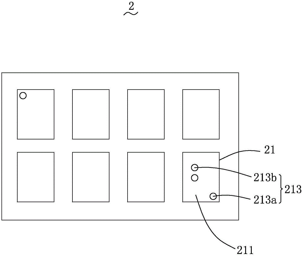
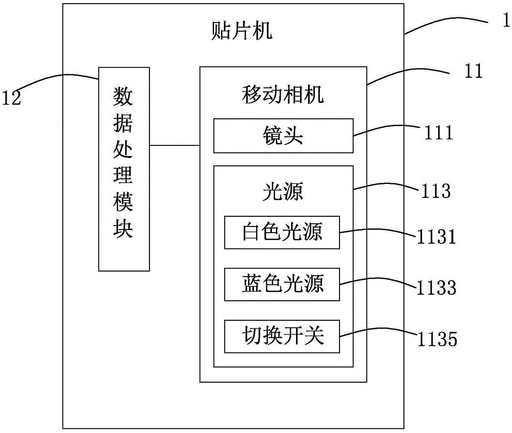
[0033] Please refer to figure 1 and figure 2 ,in, figure 1 It is a structural schematic diagram of the circuit board puzzle applied to component placement by the chip mounter of the present invention, figure 2 It is a structural schematic diagram of the placement machine of the present invention. The circuit board assembly 2 is assembled from a plurality of circuit boards 21 . Assembling a plurality of circuit boards 21 into one body facilitates simultaneous printing, patching and furnace passing of multiple circuit boards 21, saving production time.

[0034] In this embodiment, the circuit board assembly 2 is formed by splicing eight circuit boards 21 .

[0035] It can be understood that there is no limit to the number of the circuit boards 21 assembled into the circuit board panel 2 , and any number of the circuit boards 21 assembled into one b...


PUM


Abstract

The invention provides a surface mounting machine. The surface mounting machine comprises a mobile camera and a data processing module. The mobile camera is electrically connected with the data processing module. The mobile camera is used for identifying the reference points on circuit boards. The data processing module is used for analyzing reference point information to generate surface mounting coordinates. The mobile camera comprises a lens and a light source. The light source comprises a blue light source. The light source is used for irradiating the circuit boards. The lens is aligned with the circuit boards. The invention also provides a surface mounting method applying the surface mounting machine. According to the surface mounting method, the blue light source of the surface mounting machine is utilized to perform component surface mounting of circuit board splicing boards. Compared with machines in the prior art, the surface mounting machine has high identification capacity for solder paste, and the surface mounting method significantly enhances efficiency of surface mounting and significantly reduces the defects of surface mounting.

Description

technical field [0001] The invention relates to the field of electronic technology, in particular to a placement machine and a placement method thereof. Background technique [0002] Surface mount technology SMT (SurfaceMountedTechnology) has penetrated into various fields as a new generation of electronic assembly technology. SMT products have the advantages of compact structure, small size, vibration resistance, impact resistance, good high-frequency characteristics, and high production efficiency. SMT has occupied a leading position in the circuit board assembly process. [0003] As the size of the assembled components becomes smaller, the packing density becomes higher and higher. False soldering after reflow soldering due to misalignment of solder paste printing and defects in erection are increasing. When components are mounted, the center point of the solder paste is used as the center point of the component mounting, which can reduce the poor soldering caused by t...

Claims


Application Information

Patent Timeline
Patent Type & Authority Applications(China)
IPC IPC(8): H05K3/30
CPCH05K3/303H05K2203/166
Inventor 贺冬春蔡志浩孟昭光袁永仪王群庚
Owner DONGGUAN HAOYUAN ELECTRONICS CO LTD
Why Eureka
Try Eureka