Distribution of space-vector PWM conduction losses

a space-vector and conduction loss technology, applied in the field of switching system for generating sinusoidal signals, can solve the problems of high thermal stress of the unit, inability to evenly distribute the conduction loss, and the major drawback of pattern b

Inactive Publication Date: 2002-04-18
GE HYBRID TECH
View PDF0 Cites 41 Cited by
  • Summary
  • Abstract
  • Description
  • Claims
  • Application Information

AI Technical Summary

Problems solved by technology

Unfortunately, pattern B has one major drawback.
This results in a high thermal stress of the unit.
Unfortunately, this pattern does not distribute the conduction losses evenly over one PWM period.
The consequence is reduced current capability of the inverter at low sine-wave frequencies, and a deterioration of the performance of the inverter system.

Method used


Image

  • Distribution of space-vector PWM conduction losses
  • Distribution of space-vector PWM conduction losses
  • Distribution of space-vector PWM conduction losses

Examples


Embodiment Construction

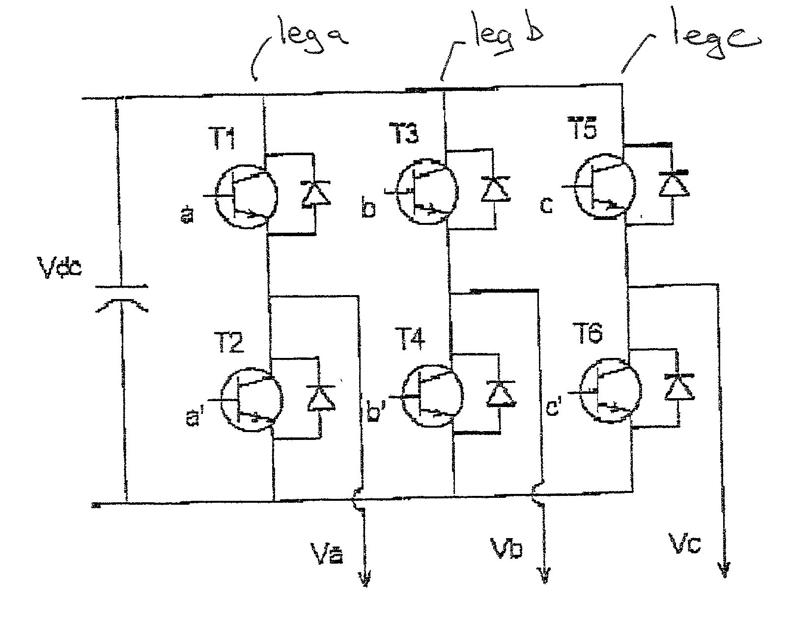
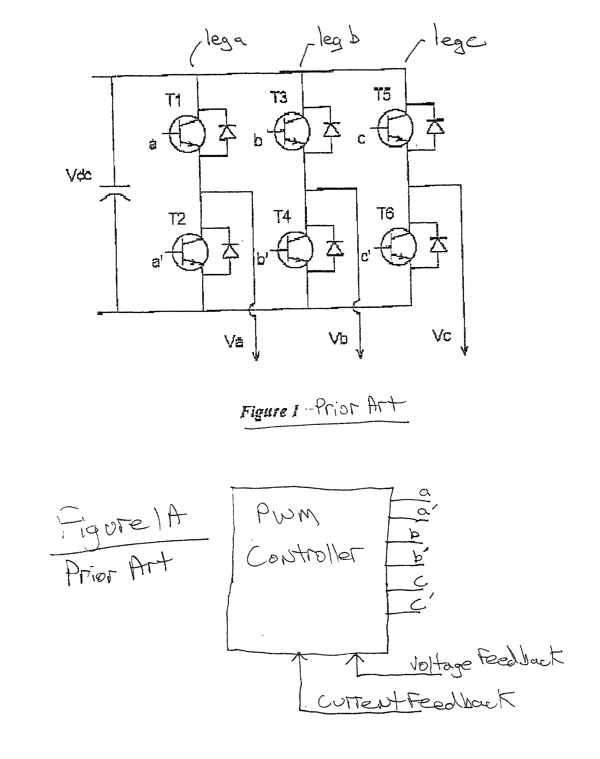
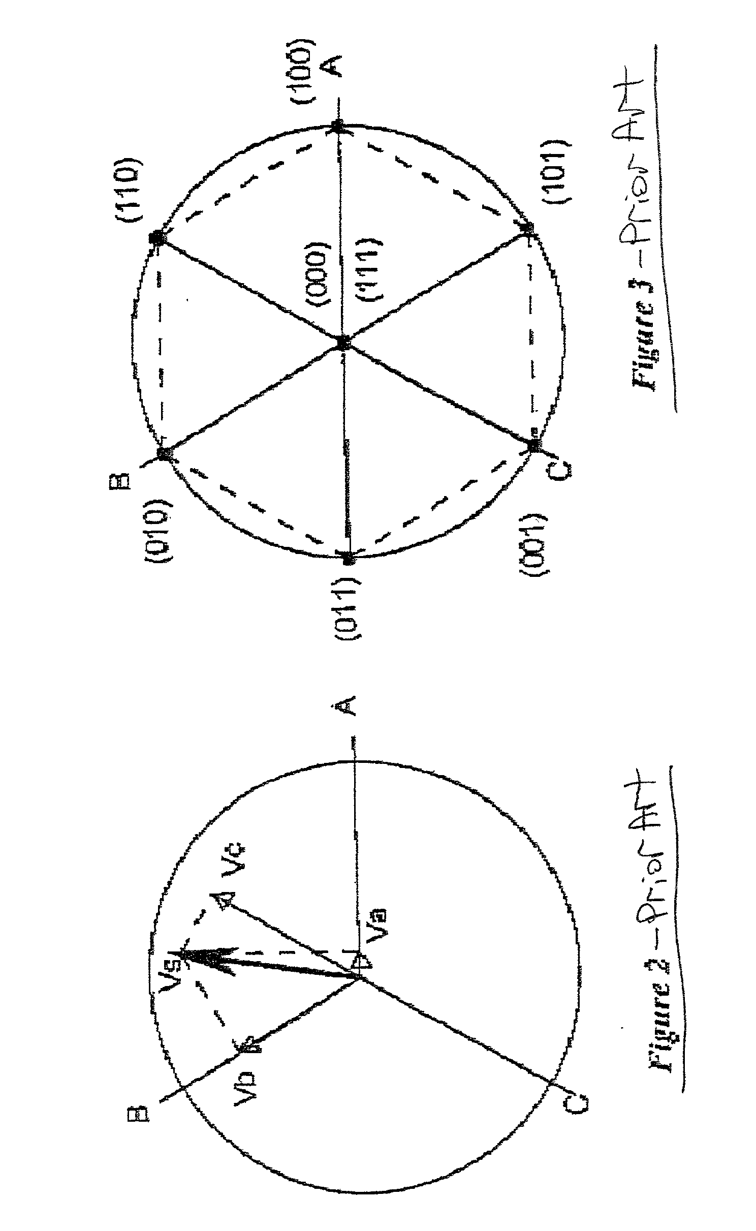
[0024] It is assumed herein that a generic PWM controller (as shown in FIG. 1A) is operating the switches depicted in FIG. 1. PWM controllers are well-understood in the art, and all such controllers are deemed within the scope of the present invention. This controller is modified by the present invention to generate the switching pattern described below. Switching pattern B of FIG. 5 offers an additional degree of freedom. As shown in FIG. 6, the sequence of the two non-zero vectors components can be permutated. On the left pattern in the FIG. 6, vector component (100) is followed by vector component (110). This is a counter-clock-wise sequence, according to the hexagon in FIG. 3. The other possibility consists in starting with vector component (110) and then switching clockwise to component (001), as shown on the second half of FIG. 6. The two directions of component sequence rotation result in different zero-vectors ((000) versus (111)) being used as components, and also in a diff...


PUM


Abstract

A voltage source inverter generating a poly phase AC signal is provided that includes an SVPWM controller. The controller is adapted to modify the switching pattern at low sine-wave frequencies creating a more even distribution of the conduction losses. The switching pattern periodically changes the sequence (or rotational sense) of the space vector components from clock-wise to counter-clock-wise direction, and vice-versa.

Description

[0001] This application claims priority from Provisional Application Serial No. 60 / 240,552, filed Oct. 13, 2000, and assigned to the same assignee.1. FIELD OF THE INVENTION[0002] The present invention relates to a switching system for generating a sinusoidal signal, and more particularly, to a space-vector pulse width modulation switching technique for generating polyphase AC signals that reduces stress in any given leg during low frequency operation.2. BACKGROUND OF THE INVENTION[0003] FIG. 1 shows the structure of a three-phase voltage-source inverter (VSI). While the input to the inverter is a DC voltage Vdc, the output consists of the three phases Va, Vb and Vc. The inverter has six power switches (T1-T6), which will be called power switches. The power switches may include anti-parallel diodes, as is understood in the art. By means of these switches each phase can be connected either to the upper or lower DC voltage rail. The power switches are controlled by three binary gate si...

Claims


Application Information

Patent Timeline
Patent Type & Authority Applications(United States)
IPC IPC(8): H02M7/5387
CPCH02M7/53875Y02B70/1491H02M2007/53876H02M2001/0048Y02B70/10H02M1/0048H02M7/53876
Inventor ARNET, BEAT J.DEYST, JOHN P.
Owner GE HYBRID TECH
Why Eureka
Try Eureka