Method of and apparatus for the elimination of the effects of inertial interference in force measurement systems, including touch-input computer and related displays employing touch force location measurement techniques

a force measurement system and inertial interference technology, applied in the field of touch input computer and related displays, can solve the problems of inability to achieve the effect of inertial interference, and inability to achieve the effect of reducing the number of inertial interferen

Inactive Publication Date: 2002-05-02
3M INNOVATIVE PROPERTIES CO
View PDF13 Cites 99 Cited by
  • Summary
  • Abstract
  • Description
  • Claims
  • Application Information

AI Technical Summary

Benefits of technology

0015] It is accordingly an object of the invention, therefore, to provide a new and improved method of and apparatus for measurement of forces that are immune to disturbin

Problems solved by technology

Since the force creating this acceleration passes through the device, the device output can no longer accurately reflect the unknown force.
Where such combinations are, however, unavoidable, two prior art techniques for amelioration are noted: viscous damping of the mechanical system itself, and linear filtering of a measurement signal derived therefrom.
Both damping and filtering typically provide faster measurement than can be acheived with no ameliorating technique: but not so fast as could be obtained were there no inertial interference present, or if there were some way to estimate such interference sufficiently accurately so that it could be subtracted from the total signal.
Such is not, however, the case for less secure monitor supports.
In addition, disturbances such as bumping or leaning upon an insecure table can introduce large

Method used


Image

  • Method of and apparatus for the elimination of the effects of inertial interference in force measurement systems, including touch-input computer and related displays employing touch force location measurement techniques
  • Method of and apparatus for the elimination of the effects of inertial interference in force measurement systems, including touch-input computer and related displays employing touch force location measurement techniques
  • Method of and apparatus for the elimination of the effects of inertial interference in force measurement systems, including touch-input computer and related displays employing touch force location measurement techniques

Examples


Embodiment Construction

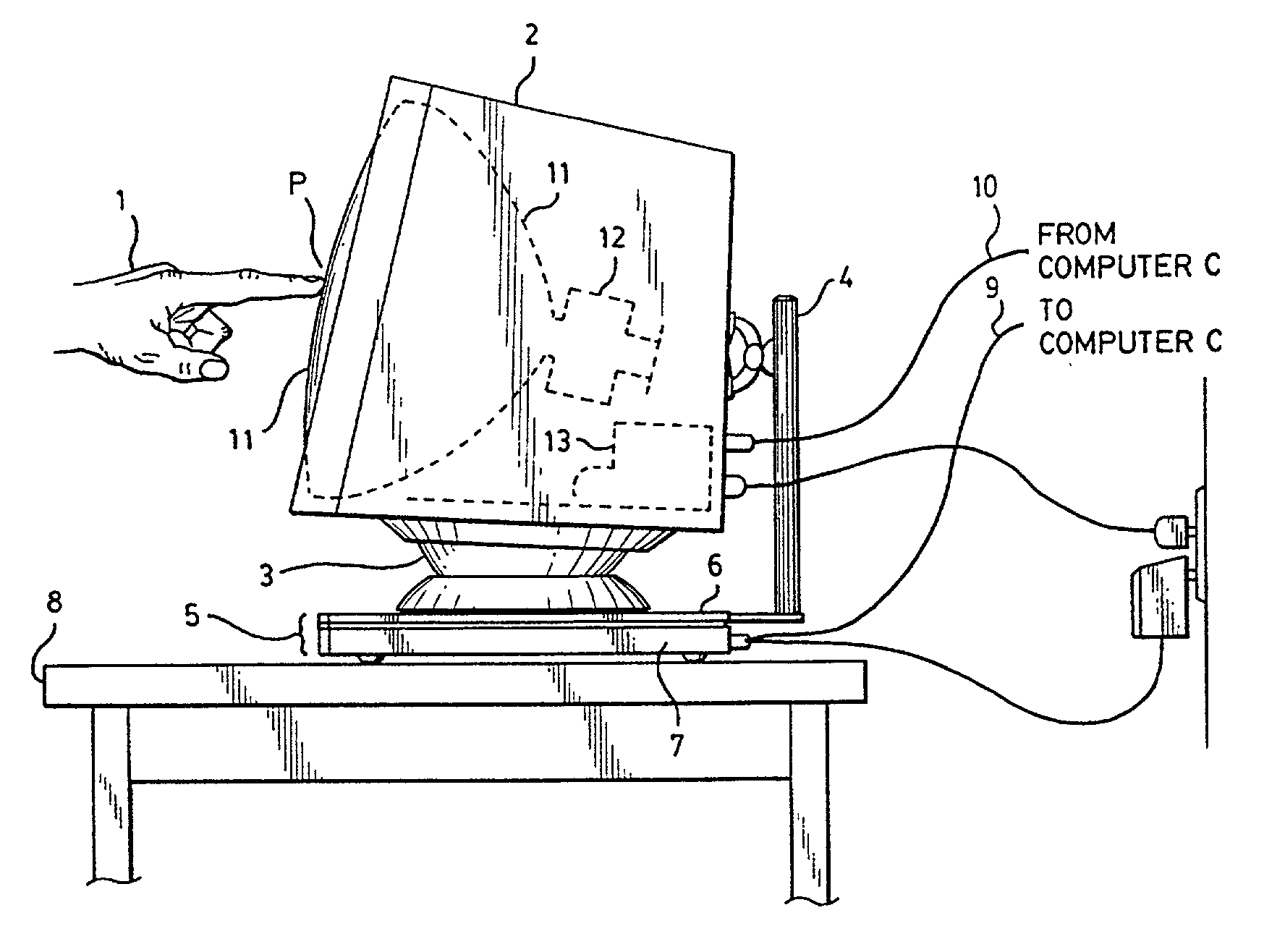
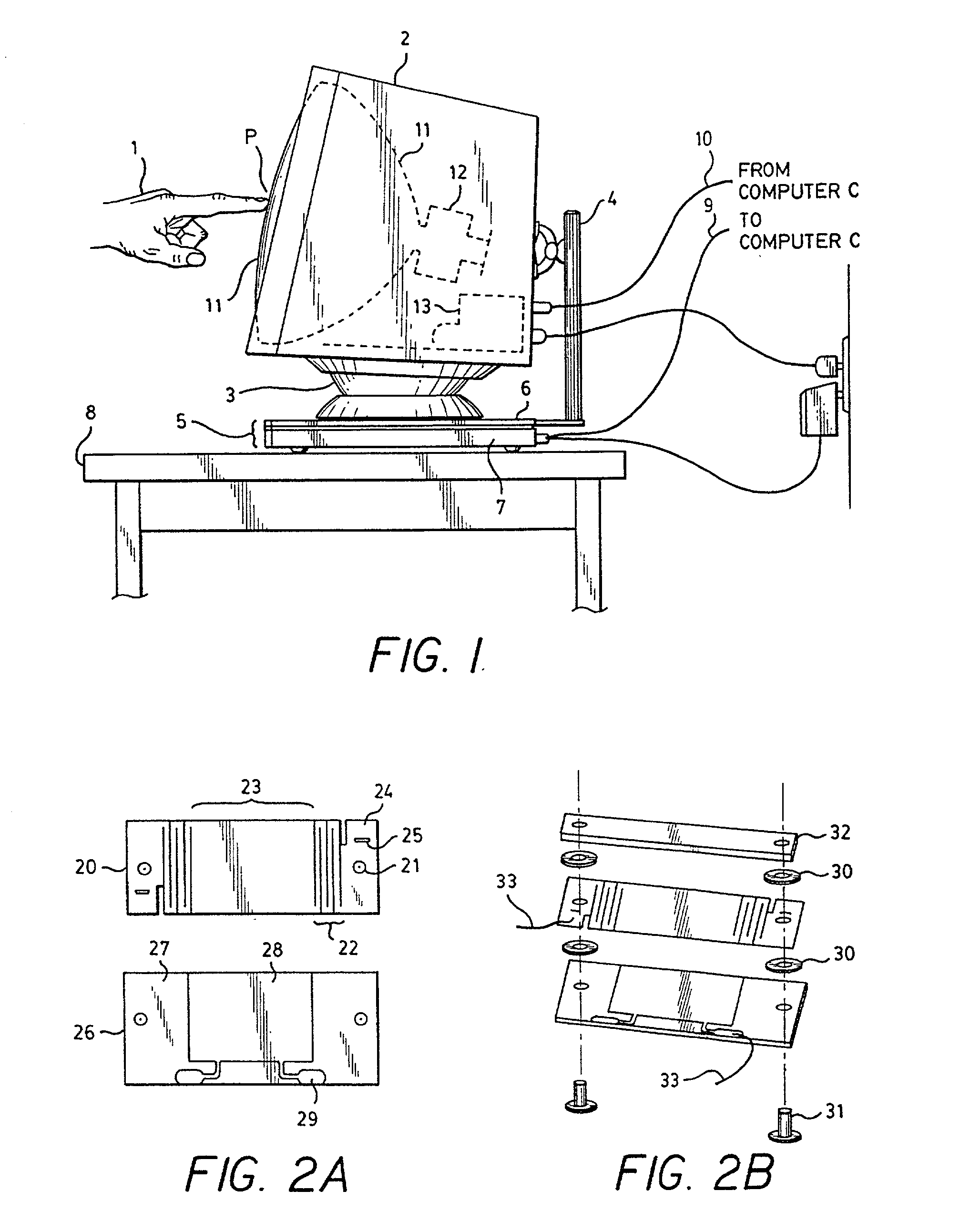
[0036] The preferred embodiment embraces the system of my said copending application, now modified to incorporate the improvement of the current invention. These improvements, as before summarized, reside in the novel type and arrangement of accelerometer capacitances as additional input channels, as shown in FIG. 4; and the extension of the firmware processing performed in the microprocessor system to support the method of the invention, as flowcharted in FIG. 5. In addition, the static sensor channels have been increased in number and the associated sensors relocated to the corners with pairs of horizontally mounted coil springs now employed.

[0037] FIG. 1 depicts the force and torque sensing platform 5 in use as a computer touch input device for locating and otherwise measuring touches delivered to the display device 2, shown as a CRT display montior 11. The touch force generated by the user's hand 1 at point P passes through CRT display monitor 2, then in parallel through a tilt-...


PUM


Abstract

A method and apparatus is disclosed, particularly, though by no means exclusively, useful in touch-screen computer CRT display systems and the like, and more generally in other force and/or torque measurement systems, as in weighing and the like, in which (1) lineal and/or rotational acceleration of the system is sensed in response to inertial interference effects such as tilt or movement that introduce errors into the force and/or torque measurements, and/or (2) inertial error correction from the force data itself is obtained, such as derivative order corrections; and such data is used to correct the force and/or torque measurements. A novel calibration technique for deriving appropriately descriptive coefficients to the particular system for the correcting data, is also disclosed.

Description

[0001] The present invention relates to the use of force measurement techniques, as in touch screen or other touch input computer cathode ray tube (CRT) or related displays to locate the points of touch on the face of the display, and under adverse circumstances where the display apparatus is rather heavy and imperfectly or poorly or insecurely supported or mounted so as to be subject to inertial interference effects, such as vibration or sway, that may cause errors in the force measurement and resulting computed touch location.[0002] While directed, accordingly, to obviating such inertial interference effects and rendering the force measurements immune to the disturbing effects of movement of the mass supported by the force measuring apparatus, as from such unsteady mountings or supports for the force measuring apparatus, the invention even more broadly finds use also with analagous problems arising in other force measuring applications, as well; such as, for example, those of weig...

Claims


Application Information

Patent Timeline
IPC IPC(8): G06F3/033G06F3/041
CPCG06F3/0418G06F3/041G06F3/04186G06F3/04182G06F3/04142
Inventor ROBERTS, JERRY B.
Owner 3M INNOVATIVE PROPERTIES CO
Why Eureka
Try Eureka