

Discrete-time system and method for induction motor control
- Summary
- Abstract
- Description
- Claims
- Application Information
AI Technical Summary
Problems solved by technology
Method used
Image

Examples
Embodiment Construction
[0016] 1. Problem Formulation
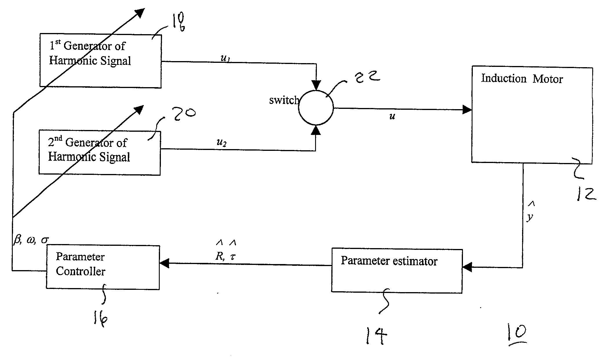
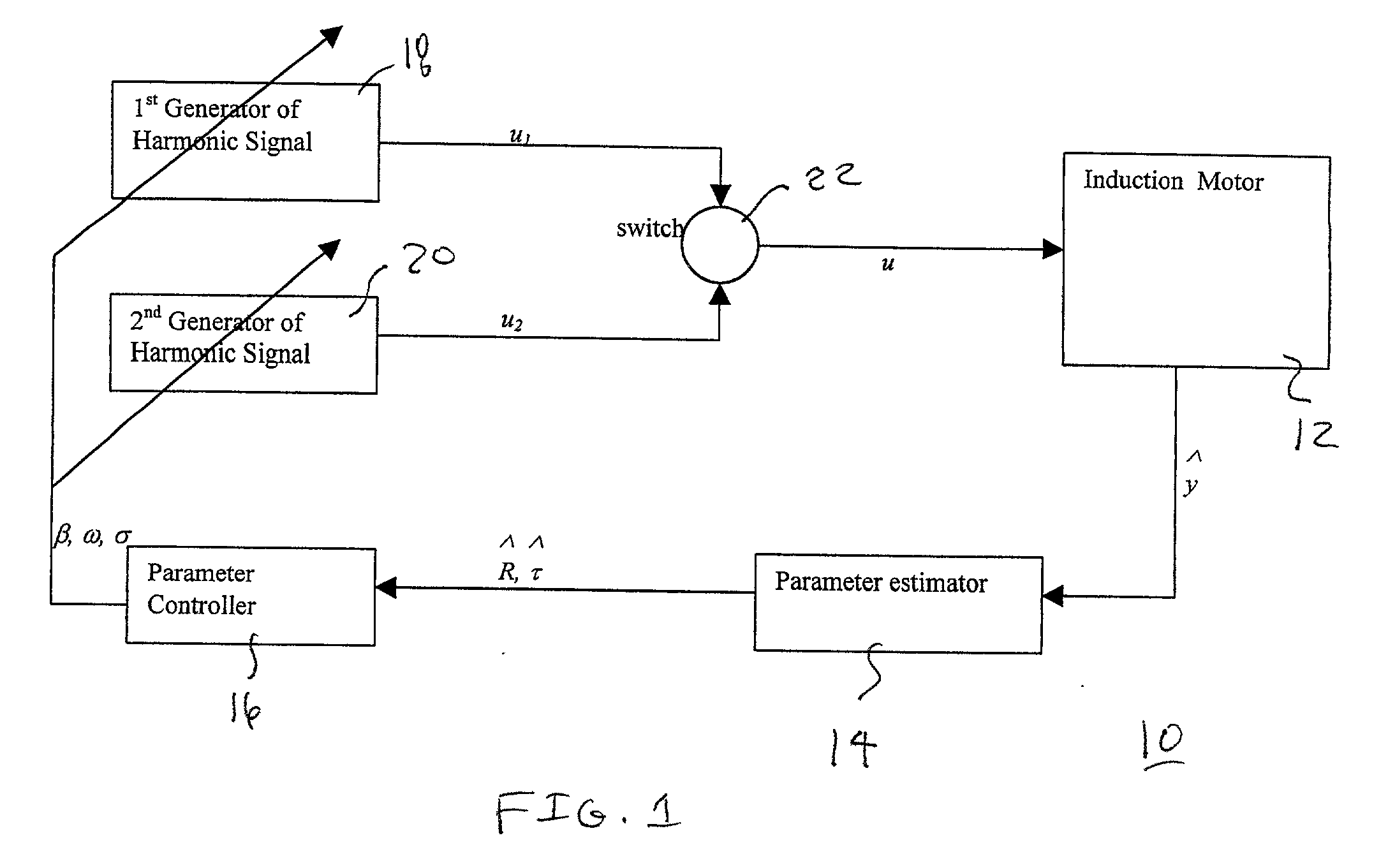
[0017] To understand the theory behind the novel control algorithm that is employed in the preferred embodiment of the present invention, the dynamic model of a current fed induction motor needs to be considered first. In its simplest formulation, with disturbances added to all channels, the model takes the form: 1 x . = Rx + Ru + 1, ( 1 ) y . =u T Jx - + 2, ( 2 ) y ^ = y + 3, ( 3 )
[0018] where 2 x = [ x 1 x 2 ] IR 2
[0019] is the rotor flux vector 3 u = [ u 1 u 2 ] IR 2
[0020] are the stator currents, .tau. is the load torque, R is the rotor resistance, y and 4 y ^
[0021] are the true and measured rotor velocity respectively, .xi..sub.1, .xi..sub.2, .xi..sub.3 are non-differentiable, nonmeasurable disturbances, 5 J = [0- 1 1 0] .
[0022] The values of R and .tau. may be unknown.
[0023] To simplify the expressions below, and without loss of generality for the purposes of this analysis, all motor parameters have been set to unity except rotor resistance and loa...
PUM
 Abstract
Description
Claims
Application Information