Golf club

a technology for golf clubs and clubs, applied in golf clubs, sports equipment, manufacturing tools, etc., can solve the problems of excessive welding beading, too small thickness of welded portions, and front edge of crown likely to sink toward the insid

Inactive Publication Date: 2002-05-09
THE YOKOHAMA RUBBER CO LTD +1
View PDF0 Cites 147 Cited by
  • Summary
  • Abstract
  • Description
  • Claims
  • Application Information

AI Technical Summary

Problems solved by technology

When welding such thin separate shell together, there occurs a problem that heat by the welding causes deformation.
More specifically, when welding a crown to a face, a front edge of the crown is likely to sink toward the inside.
In that case, excessive grinding would be needed as a post-processing to obtain a predetermined configuration, so that the resultant thickness of welded portions becomes too small.
As a result, a golf club head thus produced is likely to become irresistible to impact at the time of striking balls, resulting to a likelihood to cause cracks therein.
On the other hand, while the peripheral edges of a plurality of metallic shells are welded together in metal wood golf clubs, welding is performed by abutting the adjacent peripheral edges to one another, so that there is another problem that an excessive amount of welding bead enters inside.
If beads are repeatedly heaped up this way, more welding heat is applied due to the welding, so that the undesirable deformation is more likely to occur.
On the other hand, if the excessive welding bead is heaped, then it would be difficult to visually confirm the configuration of parts where respective shells are joined.
Further, there would occur a further problem that the applied heat causes a change in strength property of titanium alloy material so that the fragility is increased, thus leading to the possible destruction of the neighborhood of the parts to bewelded.
Even though non-solution treatment material is used, yet the welding bead is likely to cause deformation to some extent.
According to the prior art, however, there still remains a problem that when joining respective thin separate shells together by welding, they are deformed due to the heat in welding.
Further, the prior art involves a further problem that as one of the members to be abutted is provided with projections, and beads are buried in recesses formed between the projections, excessive amount of welding beads is likely to enter the inside through the recesses.

Method used


Image

  • Golf club
  • Golf club
  • Golf club

Examples


first embodiment

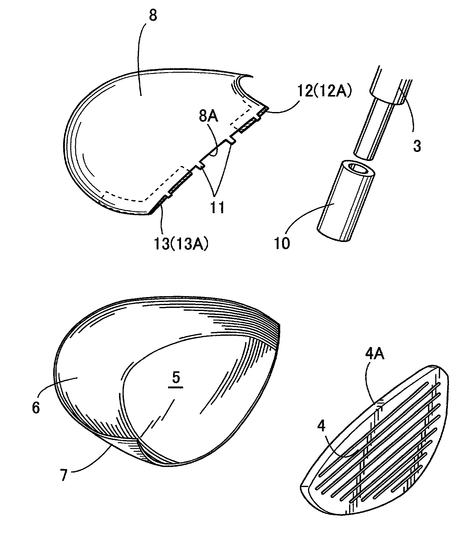
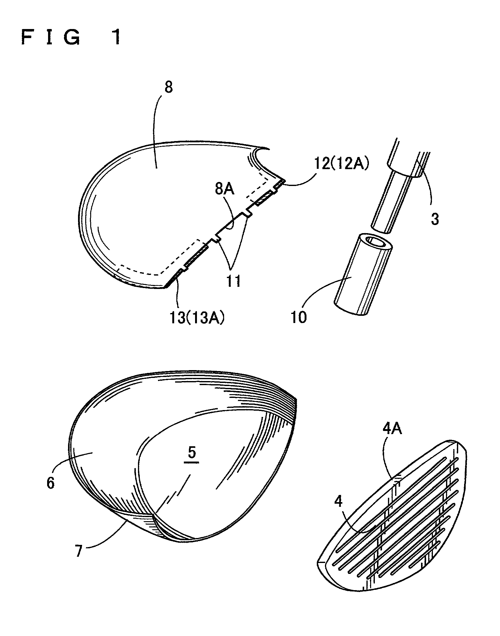
[0025] In FIGS. 1 to 3 showing the invention, a metallic wood golf club commonly known as "metal wood club", comprises a head 1 having a hosel 2 serving as a shaft attachment portion and a shaft 3 connected to the hosel 2. The head 1 is integrally formed by joining a plurality of metallic shells together. In the present embodiment, such metallic shells consist of: a face shell 4 on a front; a sole and side-peripheral shell 7 forming a sole 5 and a peripheral side portion 6; and a crown shell 8, which are made of beta type titanium alloy, respectively, and joined together by welding the respective peripheral edges one another. In the meantime, the head 1 has a hollow portion 9 with a shaft attachment pipe 10 disposed therein through the hosel 2, while a lower portion of the shaft 3 is inserted into said pipe 10. The thickness of the crown shell 8 is smaller than that of the sole and peripheral side shell 7, while the thickness of the sole and peripheral side shell 7 is smaller than t...

second embodiment

[0036] In the second embodiment, a reinforcing member 21 is integrally fixed to the inside of the front edge 8A of the crown shell 8 along the edge thereof. This reinforcing member 21 is disposed along an entirety of the front edge 8A, i.e., continuously from one side of the front edge 8A to the other side thereof, having a thickness of about 1 mm, for example, which is nearly as thin as the front edge 8A, and a width of about 5 mm. In the present embodiment, the reinforcing member 21 is integrally provided by spot welding at both sides of the front edge 8A, having a front edge 21A protruding from the front edge 8A. The projection length of the reinforcing member 21 is about 1 mm, for example, which is smaller than that of the projection 11.

[0037] Accordingly, when welding the upper edge 4A of the face shell 4 to the front edge 8A of the crown shell 8, the distal end of the reinforcing member 21 is abutted to the rear face of the face shell 4 while the projections 11 are allowed to ...

third embodiment

[0039] In the third embodiment, cladding 31 is integrally provided in advance on the inside face of the front edge 8A of the crown shell 8, said cladding 31 being provided along the edge 8A only. The cladding 31 is provided by putting weld bead, along a part or entire length of the front edge 8A, having a thickness of about 1 mm, for example, nearly as thin as the front edge 8A, and a width of about 5 mm.

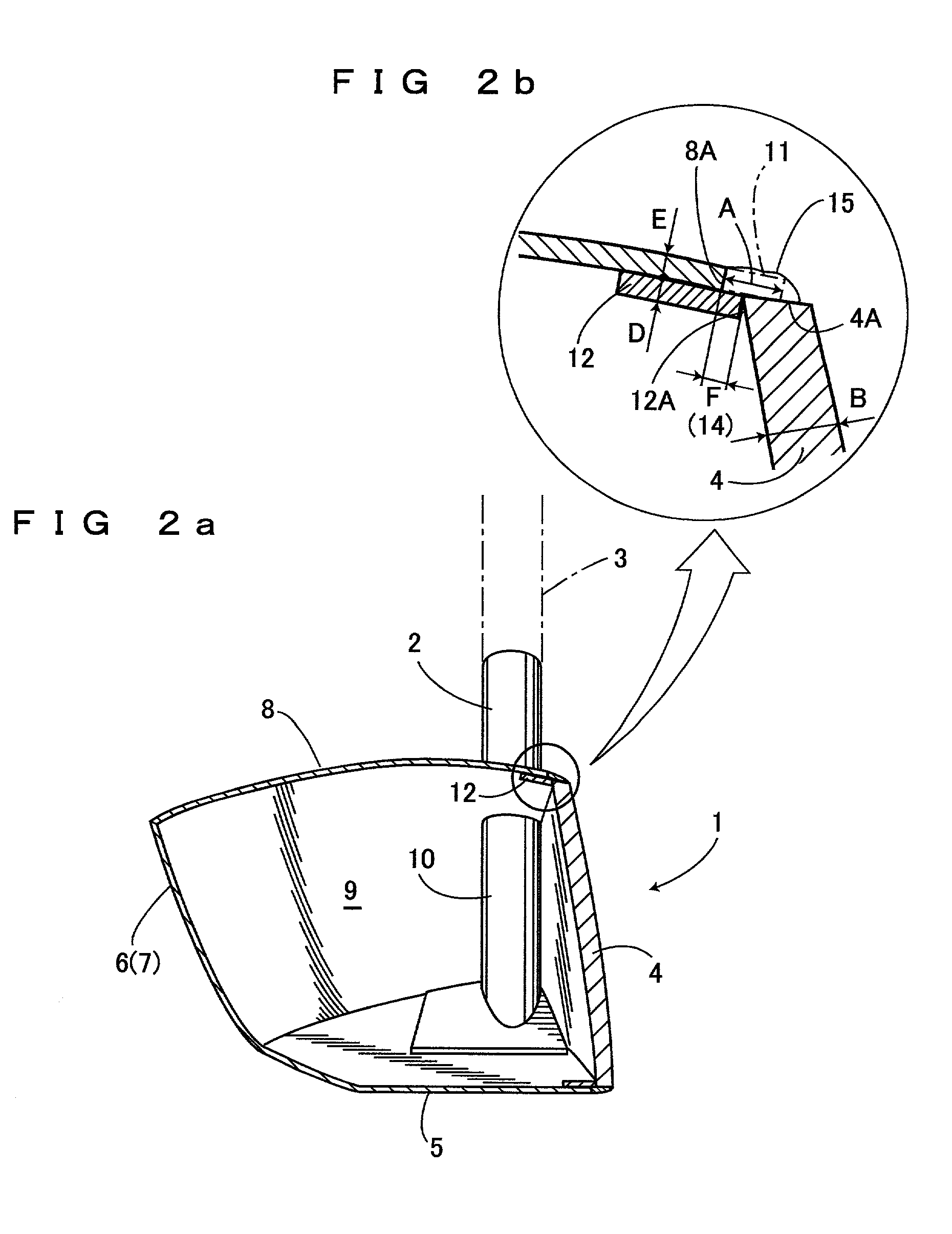
[0040] Accordingly, when welding the upper edge 4A of the face shell 4 to the front edge 8A of the crown shell 8, the upper edge 4A of the face 4 is abutted to the front edge 8A of the crown shell 8, and then, welding is carried out with the beads 15 being placed between the upper edge 4A and the front edge 8A. Thus, the front edge 8A can be reinforced by the cladding 31 when the front edge 8A side is exposed to the risk of thermal deformation by the welding heat.

[0041] Specifically, in a golf club comprising the head 1 having the shaft 3 connected thereto, said head 1 being integra...


PUM

PropertyMeasurementUnit
widthaaaaaaaaaa
thicknessaaaaaaaaaa
widthaaaaaaaaaa

Abstract

A golf club which comprises a head which is less deformable by the heat in welding. Separate reinforcing members 12 and 13 are provided on inner surface of a front edge 8A of a crown shell 8. Thus, the front edge 8A side is thickened and then the upper edge 4A of the face shell 4 is joined to the front edge 8A of the crown shell 8, by welding. The front edge 8A of the crown shell 8 is formed with a plurality of projections 11 which are anchored by the upper edge 4A of the face shell 4. front edge 8A of the crown shell 8 is thickened by adding the thickness of the reinforcing members 12, 13 to the thickness of crown shell 8 itself. Thus, thermal deformation and the sinking of the front edge 8A at the time of welding can be prevented, thus enabling the upper edge 4A to be joined to the front edge 8A as designed.

Description

[0001] 1. Field of the Invention[0002] The present invention relates to a golf club with a head made of a plurality of separate shells, having a shaft connected thereto.[0003] 2. Description of the Prior Art[0004] Conventionally, in order to produce wood golf club heads or so-called "metal Wood", it is known art to join a plurality of metallic shells together. In those types of heads, respective peripheries of plural metallic shells are integrally welded to one another.[0005] As golf club heads are progressively large-sized, with lower centers of gravity thereof being pursued, respective separate shells for constructing a head also are getting thinner and thinner. For example, in the case that a beta titanium alloy is used, face is normally as thin as 2.5 to 3.0 mm, sole and crown are each as thin as 1 mm or below. When welding such thin separate shell together, there occurs a problem that heat by the welding causes deformation. More specifically, when welding a crown to a face, a f...

Claims


Application Information

Patent Timeline
Patent Type & Authority Applications(United States)
IPC IPC(8): A63B53/02A63B53/04A63B102/32B23K31/02
CPCA63B53/02A63B53/04A63B2053/0416A63B2053/0437A63B2209/00A63B53/0466B23K31/02A63B53/0437A63B53/0416A63B60/00A63B53/0408
Inventor NISHIMOTO, TATSUOKATAHIRA, AKIRATSURUMAKI, MASAEI
Owner THE YOKOHAMA RUBBER CO LTD
Why Eureka
Try Eureka