Egr cooler

a cooler and cooler technology, applied in the field of egr coolers, can solve the problems of significant durability loss, resonance, and resonance of the tubes b>3/b>, and achieve the effects of enhancing durability, enhancing pressure loss, and enhancing the cooling effect of the exhaust gas

Inactive Publication Date: 2006-10-19
HINO MOTORS LTD +1
View PDF3 Cites 47 Cited by
  • Summary
  • Abstract
  • Description
  • Claims
  • Application Information

AI Technical Summary

Benefits of technology

[0019] The following excellent effects will be obtained according to an EGR cooler of the invention. The problem of the vibrated tubes can be overcome without causing thermal deformation of the tubes due to stagnation of the coolant water, without causing complexity in piping of the coolant water system and without increasing in pressure loss. As a result, obtainable are excellent effects such that extension of the tubes may be effected with no hindrance to enhance the cooling effect of the exhaust gas and that fatigue breakdown of the tubes for example at their opposite fixed ends may be suppressed to substantially enhance durability.

Problems solved by technology

However, the tubes 3 are supported only by the plates 2 at their opposite ends in such conventional EGR cooler so that, when the tubes 3 are extended so as to improve cooling effect through the exhaust gas 10, characteristic frequency of the tubes 3 tends to be lowered into conformity with the vibrating frequency of the engine with a disadvantageous result that the tubes 3 may be greatly vibrated due to resonance with the vibration of the engine.
When the tubes 3 are greatly vibrated due to such resonance, the respective tubes 3 tend to have fatigue breakdown for example at their opposite fixed ends, resulting in significant loss in durability.

Method used


Image

  • Egr cooler
  • Egr cooler
  • Egr cooler

Examples


Embodiment Construction

[0036] Embodiments of the invention will be described with reference to the drawings.

[0037]FIGS. 4 and 5 show an embodiment of the invention in which parts similar to those shown in FIGS. 1-3 are designated by the same reference numerals.

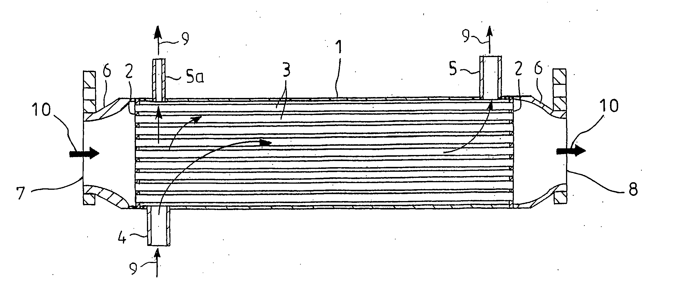
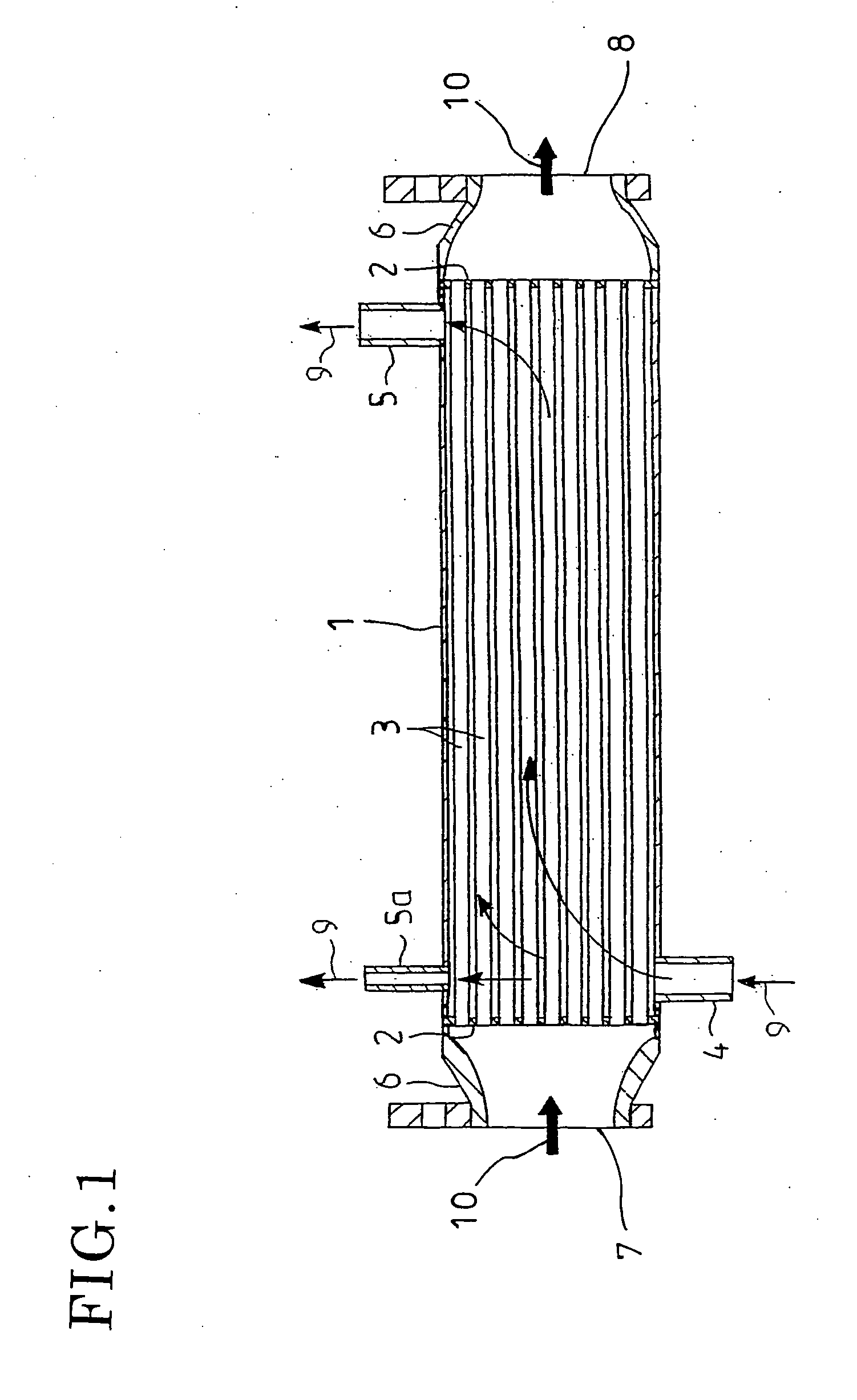
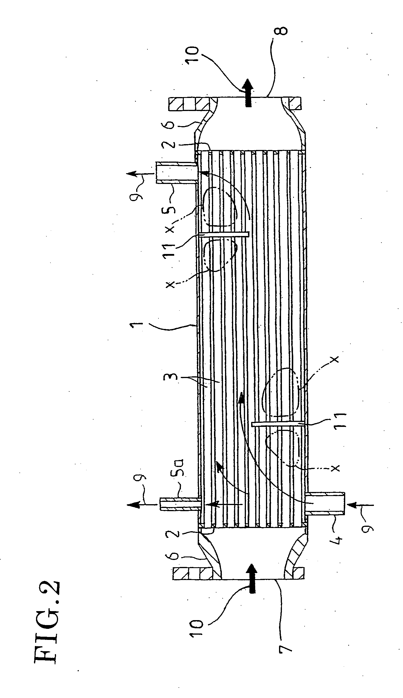
[0038] In the EGR cooler according to the embodiment, a round intermediate support plate 13 is arranged at a longitudinally intermediate position within a shell 1. Respective tubes 3 arranged multi-cylidrically about an axis of the shell 1 are penetratingly fixed by the intermediate support plate 13.

[0039] The intermediate support plate 13 is formed with a plurality of through-holes 14 for penetrating fixture of the respective tubes 3; each of the through-holes 14 are in the form of cocoon-shaped slits for penetrating fixture of the circumferentially adjacent two tubes 3 in group, the respective tubes 3 fixed to the same through-hole 14 being mutually connected by a coolant-water passage 15 for free communication of the coolant water 9.

[0040] It...


PUM


Abstract

Provided is an EGR cooler which can solve the problem of the vibrated tubes without causing thermal deformation due to stagnation of the coolant water, without complexity of piping in the coolant water system and without increase in pressure loss.
The EGR cooler comprises tubes 3 and a shell surrounding the tubes 3, the coolant water being supplied and discharged to and from the shell 1 and being passed through the respective tubes 3 so as to make heat exchange of the exhaust gas with the coolant water. In the shell 1, an intermediate support plate 13 with a plurality of through-holes 14 is arranged and mutually adjacent ones of the tubes 3 are grouped for penetratingly fixture to the through-hole 14. A coolant water passage 15 is ensured between the tubes 3 grouped and penetratingly fixed to the same through-hole 14 of the intermediate support plate 13 for free communication between the tubes 3.

Description

TECHNICAL FIELD [0001] The present invention relates to an EGR cooler attached to an EGR apparatus, which recirculates exhaust gas from an engine to suppress generation of nitrogen oxides, so as to cool the exhaust gas to be recirculated. BACKGROUND ART [0002] Known is an EGR apparatus which recirculates part of exhaust gas from an engine in a vehicle or the like to the engine to suppress generation of nitrogen oxides. Some of such EGR apparatuses are equipped with, midway of an exhaust gas recirculation line to the engine, an EGR cooler for cooling the exhaust gas since cooling of the exhaust gas to be recirculated to the engine will drop the temperature of and reduce the volume of the exhaust gas to lower the combustion temperature in the engine without substantial decrease in output of the engine, thereby effectively suppressing generation of nitrogen oxides. [0003]FIG. 1 is a sectional view showing an example of the EGR coolers in which reference numeral 1 denotes a cylindrical ...

Claims


Application Information

Patent Timeline
Patent Type & Authority Applications(United States)
IPC IPC(8): F28F9/02F28F1/10F02M25/07F28D7/00F28F9/013
CPCF02M25/0737F28D7/0066F28D7/0091F28F2265/30F28F9/0131Y02T10/121F28F2009/226F28D21/0003F02M26/32F28F9/013F28D7/00F28F9/007
Inventor SUGIHARA, HIROYUKITSUJITA, MAKOTOYAMASHITA, YOJI
Owner HINO MOTORS LTD
Why Eureka
Try Eureka