Group antenna with narrower side lobes in the horizontal plane

Inactive Publication Date: 2002-05-16
HIGHBRIDGE PRINCIPAL STRATEGIES LLC AS COLLATERAL AGENT
View PDF0 Cites 187 Cited by
  • Summary
  • Abstract
  • Description
  • Claims
  • Application Information

AI Technical Summary

Benefits of technology

[0005] There is thus a need to be able to give a column antenna in an antenna device a narrow main lobe in a way that is simpler and cheaper than what has previously been known.
[0007] By the group antenna, the column antenna, being given a narrower main lobe in the horizontal plane, the statistical probability of receiving transmissions from sources of interference in or around the horizontal plane is reduced, and it is easier to direct the transmissions of the group antenna to one or more intended subscribers.

Problems solved by technology

As a column antenna has a wide antenna beam in the sideways direction, there is a relatively high probability that a large number of sources of interference will be situated within the antenna beam, and the wide antenna beam means that it is difficult to direct the transmission only to the intended subscriber(s).
A disadvantage of this is, however, that the distribution network results in an additional cost, and that the antennas involved must be combined in a way that is difficult.

Method used


Image

  • Group antenna with narrower side lobes in the horizontal plane
  • Group antenna with narrower side lobes in the horizontal plane
  • Group antenna with narrower side lobes in the horizontal plane

Examples


embodiment 900

[0028] In an antenna device with column antennas arranged according to the invention, there can be a desire to direct the transmitted energy in such a way that the range is limited and the energy is directed more towards the recipients for whom it is intended, for example the subscribers in a cell in a mobile telephony system. FIG. 9 shows a further possible embodiment 900 of the invention that fulfils this requirement: Instead of arranging column antennas according to the invention making contact with a right cylinder that is perpendicular to the horizontal plane, which is shown in FIG. 5, the column antennas 910, 920, 930 can be arranged according to the invention along, for example, an imaginary conical surface, which means that the column antennas 910, 920, 930 will be inclined in a sideways direction according to the invention and will also be inclined "forwards", which limits the range and better directs the lobes towards the intended area of cover. For the sake of clarity, ra...

embodiment 10

[0029] FIG. 10 shows an embodiment 10 that in principle corresponds to the one in FIG. 7, but with the difference that the radiating elements are arranged on and around a conical surface, which combines the advantages of the embodiments in FIG. 7 and FIG. 9. A number of radiating elements are arranged on a conical surface 10, and combined into antennas that also are inclined in a sideways direction. FIG. 10 shows how column antennas 11 and 12 according to the invention can be made up of a number of radiating elements, 111-115 and 121-125 respectively.

[0030] The invention is not restricted to the embodiments described above, but can be varied freely within the scope of the following claims. For example, the angles at which the column antennas are inclined according to the invention can, in principle, be selected as required, and all the column antennas do not need to be inclined at the same angle. Nor does the number of radiating elements need to be the same in all the column antenna...


PUM


Abstract

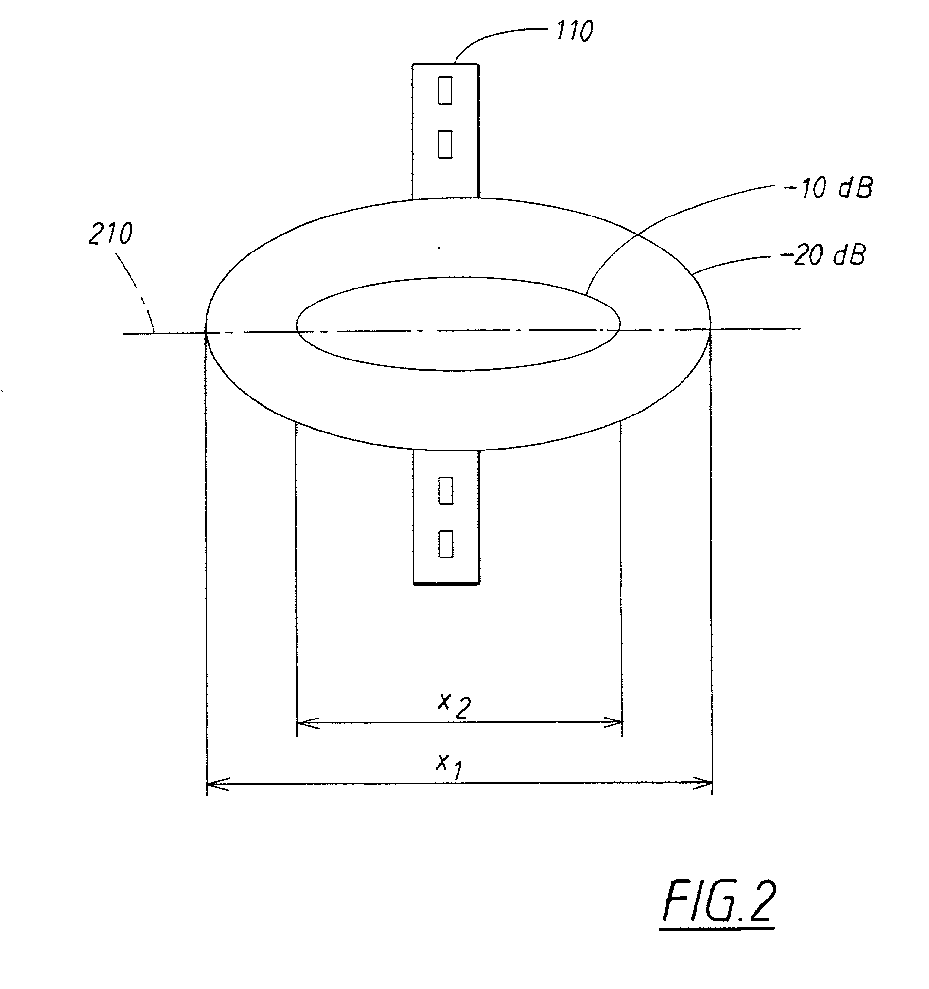
The invention relates to an antenna device comprising a group antenna (310) with radiating elements (340-347) in M rows and N columns M, where N<M, which group antenna (310) has a width measurement (b) and a height measurement (h). The group antenna (310) is so arranged in the antenna device that the projection (P) of the group antenna in the sideways direction of the antenna in the horizontal plane (210) exceeds the width measurement (b) of the group antenna, whereby the group antenna is given a narrower main lobe in the horizontal plane (210). A group antenna according to the invention can, in addition, be incorporated in an antenna device (500,700,800) which comprises an additional number of similar group antennas (510-532; 710-720; 810-820), arranged on the antenna device along a surface (730,830) that is circular or a part of a circle, arranged in such a way that the respective projections of the additional group antennas in the sideways direction of the antenna in the horizontal plane also exceed the width measurements of the respective group antennas, whereby the additional group antennas are given narrower main lobes in the horizontal plane.

Description

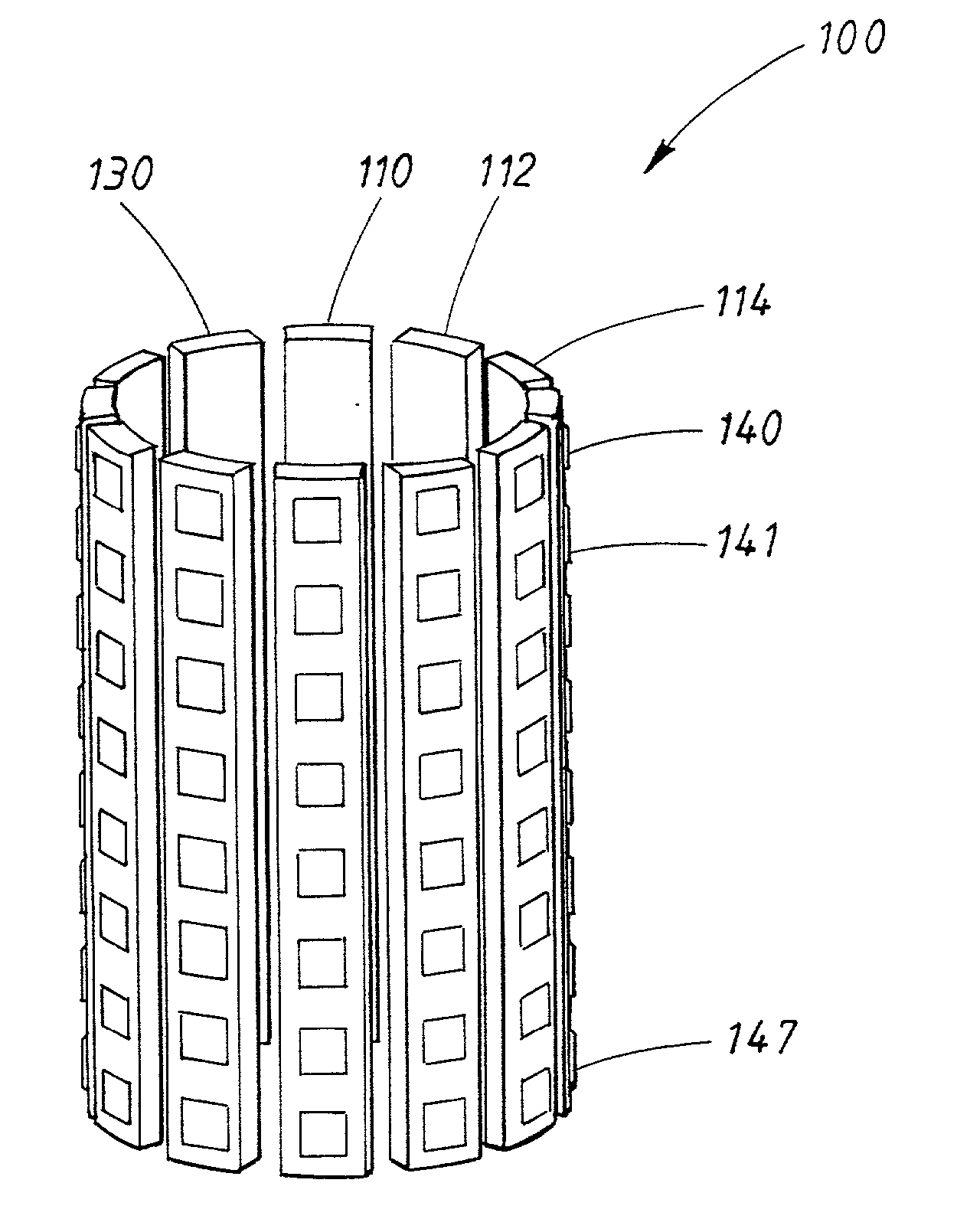
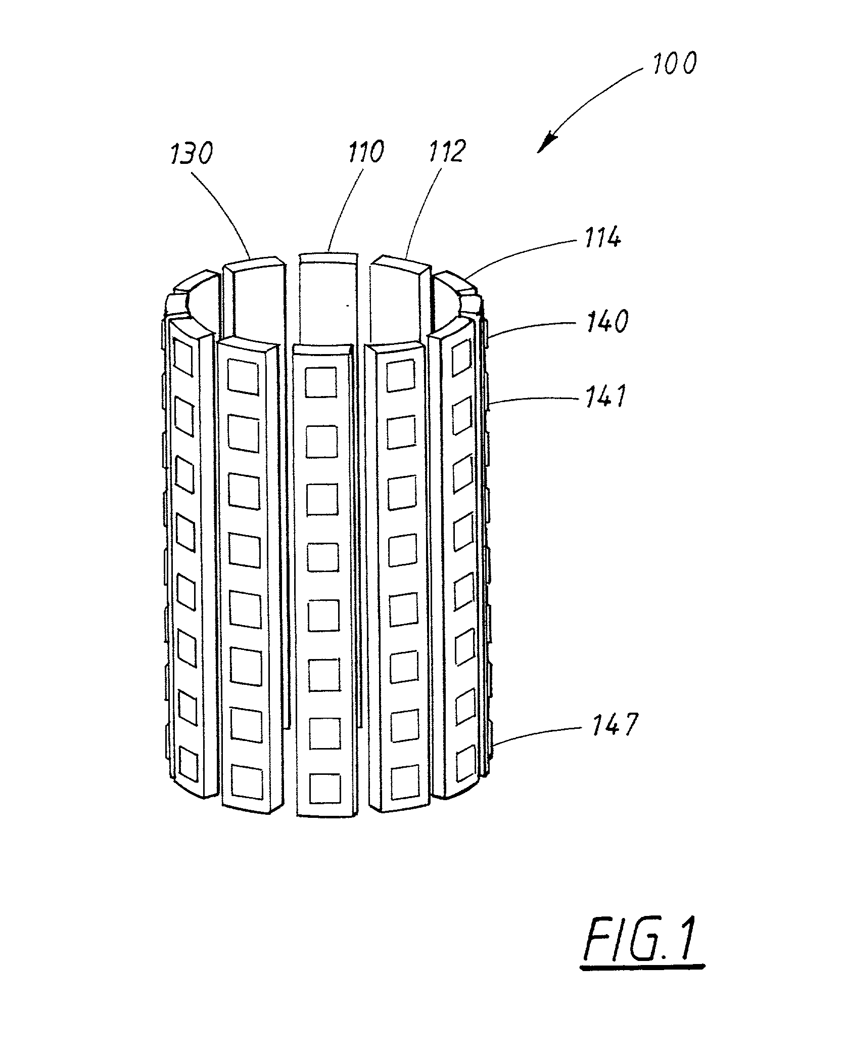
[0001] The present invention relates to an antenna device with group antennas that are given narrower main lobes in the horizontal plane in a simpler way than what has previously been known.[0002] Group antennas are a type of antennas that comprise a plurality of radiating elements, usually arranged in M rows and N columns. A common type of group antennas, here called column antennas, have considerably many more rows than columns, which gives a column antenna an antenna beam that is wide in the azimuth (sideways direction) and narrow in the vertical direction.[0003] In connection, for example, with mobile telephony, it is usual to arrange column antennas side by side in a way that gives the required coverage. As a column antenna has a wide antenna beam in the sideways direction, there is a relatively high probability that a large number of sources of interference will be situated within the antenna beam, and the wide antenna beam means that it is difficult to direct the transmission...

Claims


Application Information

Patent Timeline
IPC IPC(8): H01Q3/02H01Q21/06H01Q21/20
CPCH01Q3/02H01Q21/064H01Q21/205H01Q21/20H01Q21/065
Inventor HOOK, ANDERS
Owner HIGHBRIDGE PRINCIPAL STRATEGIES LLC AS COLLATERAL AGENT
Why Eureka
Try Eureka