Valve attached to fuel tank
- Summary
- Abstract
- Description
- Claims
- Application Information
AI Technical Summary
Problems solved by technology
Method used
Image
Examples
example no.2
EXAMPLE NO. 2
[0079] Similarly to Example No. 1, Example No. 2 also embodies a valve attached to a fuel tank according to the present invention as a liquid-fuel flow-out inhibition valve.
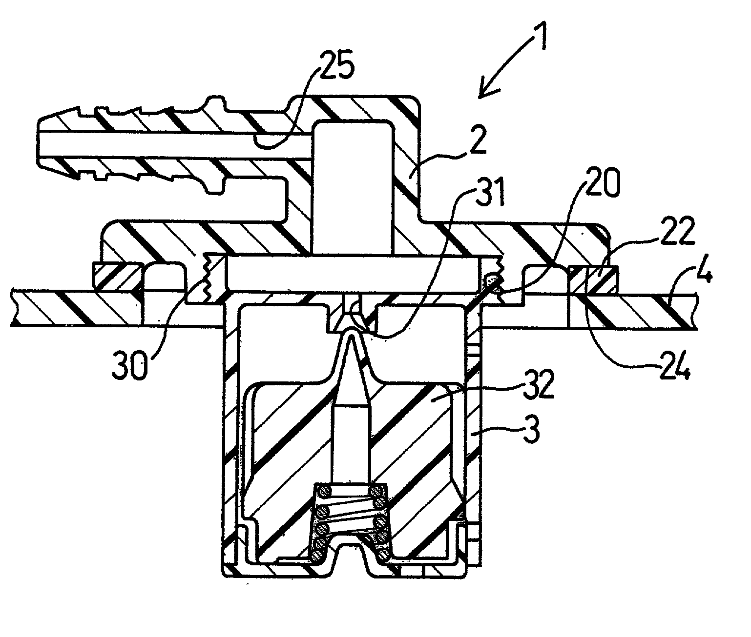
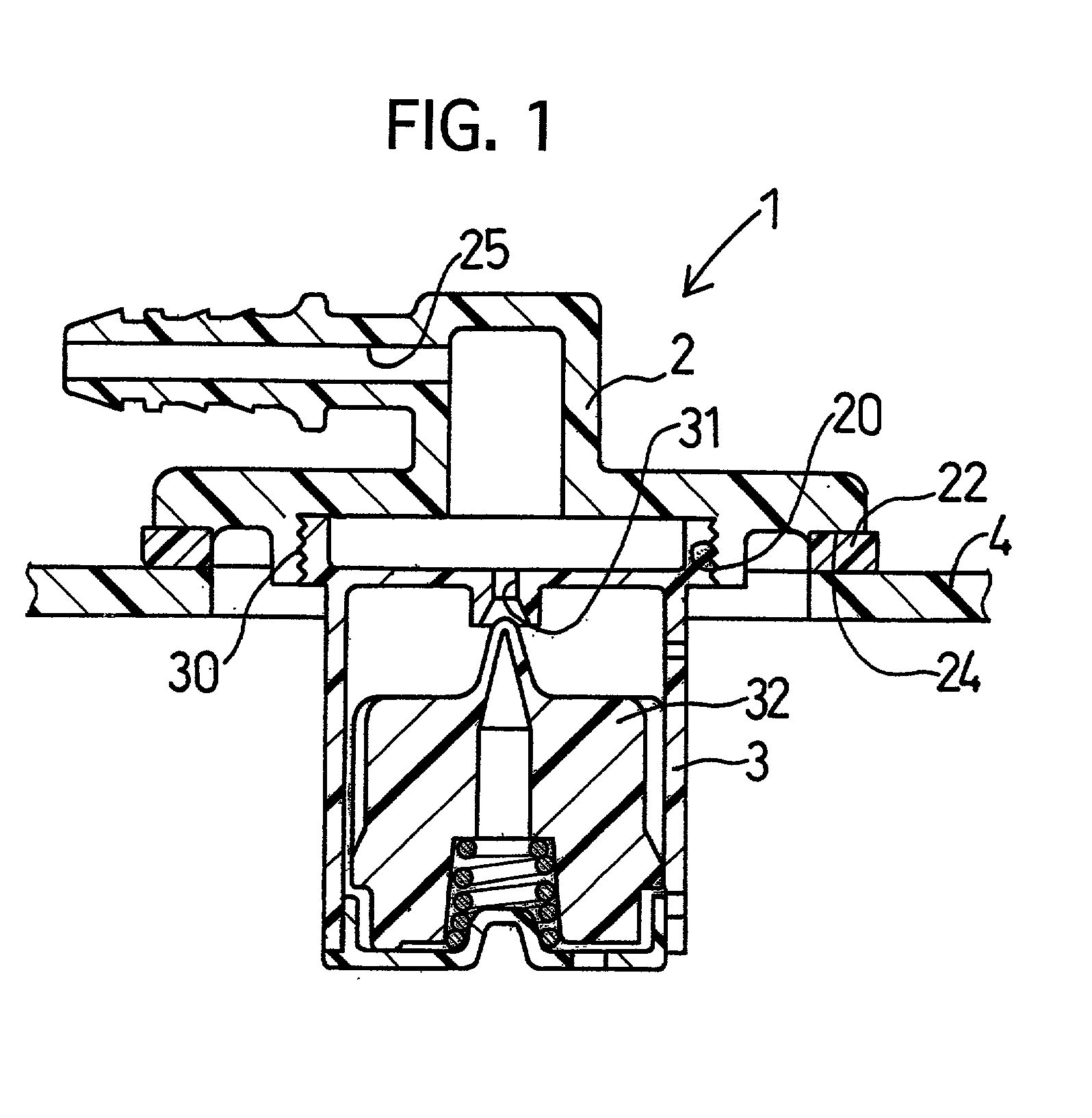
[0080] Similarly to Example No. 1 illustrated in FIG. 1, a liquid-fuel flow-out inhibition valve 1 of Example No. 2 comprises a cover 2 and a case 3. The cover 2 includes a connecting surface 24, which is to be bonded with a fuel tank 4 and which has a connector portion 22, and a flow-out passage 25, which is disposed therein. The case 3 includes an evaporator opening 31, which is disposed at the central portion in the upper surface, and a floating valve 32, which is disposed therein. Moreover, a female screw 20 is formed in an opening-end inner peripheral surface of the cover 2, and a male screw 30 is formed on an outer peripheral surface of the case 3, respectively.
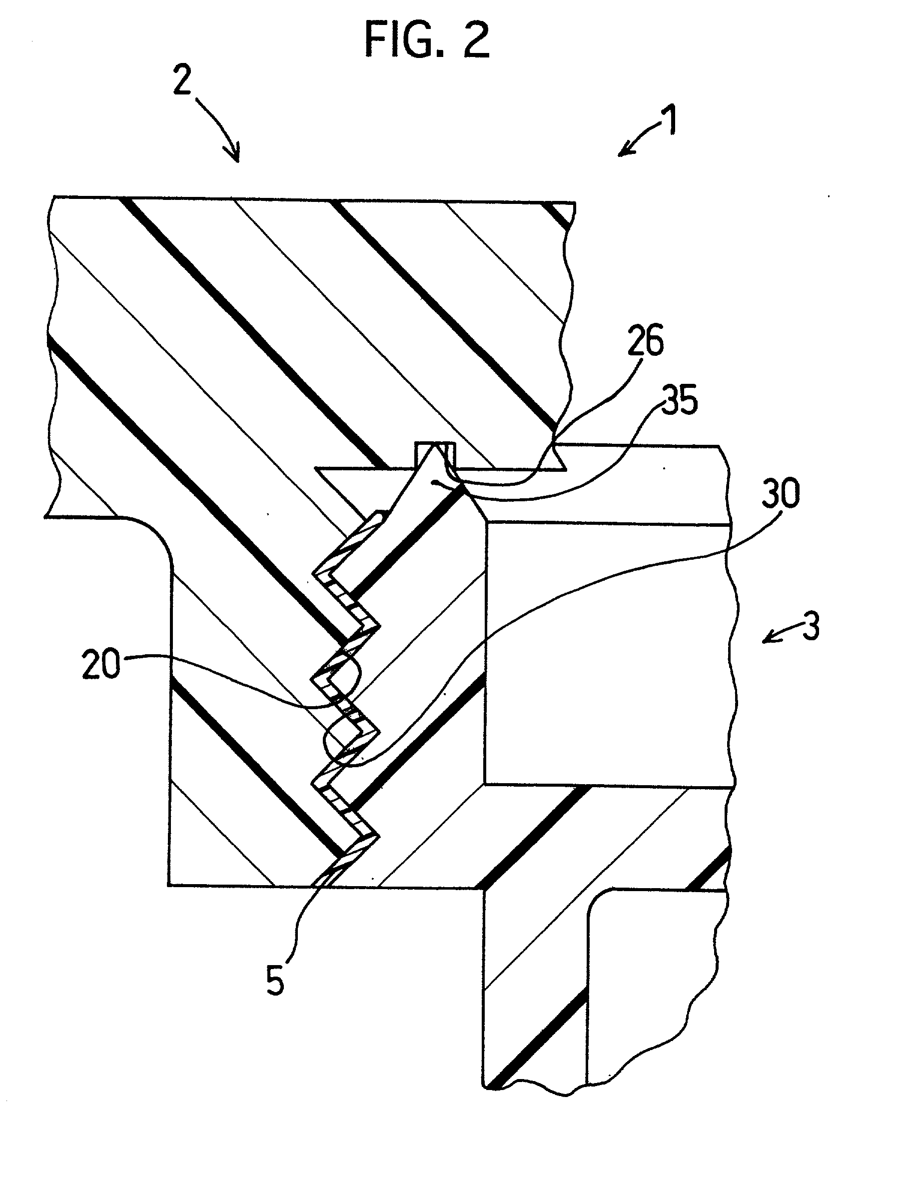
[0081] As illustrated in FIG. 2, an enlarged cross-sectional view of the liquid-fuel flow-out inhibition valve 1 of Example No. 2, the ...
example no.3
EXAMPLE NO. 3
[0090] Similarly to Example No. 1, Example No. 3 also embodies a valve attached to a fuel tank according to the present invention as a liquid-fuel flow-out inhibition valve.
[0091] As illustrated in FIG. 3, a liquid-fuel flow-out inhibition valve 1 of Example No. 3 comprises a cover 2 and a case 3. The cover 2 includes a connecting surface 24, which is to be bonded with a fuel tank 4 and which has a connector portion 22, and a flow-out passage 25, which is disposed therein. The case 3 includes an evaporator opening 31, which is disposed at the central portion in the upper surface, and a floating valve 32, which is disposed therein. Moreover, a male screw 21 is formed in an opening-end outer peripheral surface of the cover 2, and a female screw 31 is formed on an inner peripheral surface of a cylinder-shaped extended portion of the case 3, respectively.
[0092] Similarly to Example No. 1 described above, in Example No. 3 as well, the cover 2, the case 3 and the floating val...
example no.4
EXAMPLE NO. 4
[0097] Similarly to Example No. 1, Example No. 4 also embodies a valve attached to a fuel tank according to the present invention as a liquid-fuel flow-out inhibition valve.
[0098] Similarly to Example No. 3 illustrated in FIG. 3, a liquid-fuel flow-out inhibition valve 1 of Example No. 4 comprises a cover 2 and a case 3. The cover 2 includes a connecting surface 24, which is to be bonded with a fuel tank 4 and which has a connector portion 22, and a flow-out passage 25, which is disposed therein. The case 3 includes an evaporator opening 31, which is disposed at the central portion in the upper surface, and a floating valve 32, which is disposed therein. Moreover, a male screw 21 is formed in an opening-end outer peripheral surface of the cover 2, and a female screw 33 is formed on an inner peripheral surface of a cylinder-shaped extended portion of the case 3, respectively.
[0099] As illustrated in FIG. 4, an enlarged cross-sectional view of the liquid-fuel flow-out inh...
PUM
 Abstract
Description
Claims
Application Information
 - R&D
- Intellectual Property
- Life Sciences
- Materials
- Tech Scout
- Unparalleled Data Quality
- Higher Quality Content
- 60% Fewer Hallucinations
Browse by: Latest US Patents, China's latest patents, Technical Efficacy Thesaurus, Application Domain, Technology Topic, Popular Technical Reports.
© 2025 PatSnap. All rights reserved.Legal|Privacy policy|Modern Slavery Act Transparency Statement|Sitemap|About US| Contact US: help@patsnap.com


