Imaging apparatus

a technology of image signal processing and image output, which is applied in the direction of color signal processing circuits, instruments, static indicating devices, etc., can solve the problems of insufficient performance of conventional imaging apparatus or image output apparatus, insufficient image signal fidelity with respect to the chromaticity of objects in imaging operation, and inability to fundamentally reproduce the color of external chromaticity, etc., to achieve high data efficiency, expand the color area of imaging apparatus, and effectively utilize the area of triangle

Inactive Publication Date: 2002-05-23
MINOLTA CO LTD
View PDF4 Cites 22 Cited by
  • Summary
  • Abstract
  • Description
  • Claims
  • Application Information

AI Technical Summary

Benefits of technology

0024] By such a configuration, the three optical filters can have the spectral transmittance characteristics corresponding to the color matching functions when the chromaticity coordinates of the apexes of the triangle including the whole area of the visible lights on the UCS chromaticity diagram are used as the chromaticity coordinates of three principal colors in the new color system. Since the color matching functions of the new three principal colors take only zero or the positive value, no photoelectric transfer device having negative sensitivity will be necessary for realizing the spectral sensit

Problems solved by technology

Furthermore, the color of the external chromaticity cannot be reproduced fundamentally, since the negative color cannot be emitted from the television.
The disadvantages that the fidelity of the image signals with respect to the chromaticity of the object in the imaging operation is lower and that the area of the color reproduction in the image outputting is smaller become no problem in the field of private demand such as amusement.
On the other hand, in the field of service such as

Method used


Image

  • Imaging apparatus
  • Imaging apparatus
  • Imaging apparatus

Examples


Embodiment Construction

Imaging Apparatus and Optical Filters

[0054] An embodiment of an imaging apparatus and optical filters in accordance with the present invention is described.

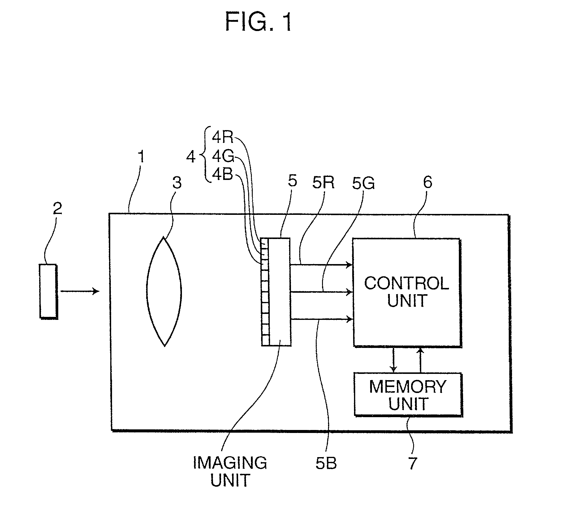
[0055] A schematic configuration of an imaging apparatus in the embodiment is shown in FIG. 1. The imaging apparatus 1 for taking a color image of an object 2 comprises a taking lens 3, a set of optical filters 4, an imaging unit 5, a control unit 6 and a memory unit 7.

[0056] The taking lens 3 focuses an image of the object 2 on a light receiving surface of the imaging unit 5. The optical filters 4 comprises a plurality of optical filters 4R, 4G and 4B which are arranged as a predetermined pattern. The imaging unit 5 includes am area sensor in which a plurality of photoelectric transfer devices are arranged two-dimensionally, and any of the optical filters 4R, 4G and 4B is disposed in front of each photoelectric transfer device. The optical filters 4 and the imaging unit 5 are integrally configured. The optical filters 4R, 4G and...


PUM


Abstract

For taking an image included in whole area of the chromaticity of the visible lights by an imaging apparatus, three kinds of optical filters respectively having spectral sensitivity characteristics corresponding to color matching functions of chromaticity coordinates of new three principal colors in a new color system is used. The chromaticity coordinates of the three principal colors satisfy that a triangle formed by the three principal colors includes whole area of visible lights on a UCS chromaticity diagram, a line binding a first apex and a second apex of the triangle circumscribes at least a part of a spectral locus of the visible lights on the UCS chromaticity diagram, a line binding the second apex and a third apex of the triangle circumscribes at least a part of the spectral locus of the visible lights on the UCS chromaticity diagram, and a line binding the first apex and the third apex of the triangle circumscribes at least a part of the purple boundary on the UCS chromaticity diagram.

Description

[0001] This application is based on patent application 2000-297151 filed in Japan, the contents of which are hereby incorporated by references.[0002] 1. Field of the Invention[0003] The present invention relates to an imaging apparatus and optical filters based on a new color system expanding area of color reproduction, and an image data converting apparatus for converting color data based on the new color system to color data based on a conventional color system.[0004] 2. Description of the Related Art[0005] Three ideal spectral sensitivity characteristics R(.lambda.), G(.lambda.) and B(.lambda.), which are obtained from chromaticity of three principal colors of a picture tube and a standard white defined, for example, in the NTSC television standard, are shown in FIG. 24. As can be seen from FIG. 24, the sensitivity characteristics R(.lambda.), G(.lambda.) and B(.lambda.) respectively have negative portions where the stimulus value (sensitivity) takes a negative value and positive...

Claims


Application Information

Patent Timeline
IPC IPC(8): G06T1/00G02B5/20H04N1/04H04N1/48H04N1/60H04N9/04H04N9/64H04N9/67
CPCH04N9/045H04N23/841
Inventor MIZUMOTO, KENJI
Owner MINOLTA CO LTD
Why Eureka
Try Eureka