Setting apparatus and setting method each for setting setting information in electric power line carrier communication terminal apparatus

a technology of communication terminal and setting information, which is applied in the direction of mechanical power/torque control, program control, ratio control, etc., can solve the problems of difficulty in identification of system setting technique of polling and selecting type, difficulty in physically specifying which operating switch terminal apparatus is installed, and difficulty in connecting plcc terminal apparatuses to the electric power line of commercial electric power

Inactive Publication Date: 2002-05-30
MATSUSHITA ELECTRIC WORKS LTD
View PDF0 Cites 140 Cited by
  • Summary
  • Abstract
  • Description
  • Claims
  • Application Information

AI Technical Summary

Problems solved by technology

In the prior art technique, however, in the above-mentioned system setting technique using DIP switches, a trouble may be caused due to setting error in the case of a great number of terminal apparatuses, for example.
On the other hand, the system setting technique of polling and selecting type has difficulty in identification in a case of a plurality of electric power line carrier communication terminal apparatuses of the same kind and the same model number.
On the other hand, when an electric power line carrier communication terminal is either (a) a PLCC terminal apparatus such as a wall-installed operating switch terminal which comprises an operating switch for turning on and off a lighting equipment or (b) a wiring equipment type PLCC terminal apparatus such as a plug-in connection type load terminal apparatus having a plug socket for an electric power load apparatus such as a ceiling adapter for lighting equipment, then these PLCC terminal apparatuses can not be easily connected to the electric power line of the commercial electric power.
However, since there exist a plurality of operating switch terminal apparatuses of the same kind and the same model number, and a plurality of numbers of plug-in connection type load terminal apparatuses of the same kind and the same model number, and this leads to difficulty in physically specifying which operating switch terminal apparatus is installed where, or which plug-in connection load terminal is to be operated by an operating switch.
However, actual management of the installation places could be realized at much expense in time and much effort at a building site in a disorderly situation.
In this case, however, it is hard in terms of product design to provide such a display on a product surface since a plug-in connection type load terminal apparatus of a wiring adapter type requires a relatively small size.
On the other hand, when such a display is provided on a side surface or a rear surface of a product, the display results in being hidden within a wall and in order to avoid this, it is also expected that installment arrangement becomes more complex for the plug-in connection type load terminal apparatuses.

Method used


Image

  • Setting apparatus and setting method each for setting setting information in electric power line carrier communication terminal apparatus
  • Setting apparatus and setting method each for setting setting information in electric power line carrier communication terminal apparatus
  • Setting apparatus and setting method each for setting setting information in electric power line carrier communication terminal apparatus

Examples


embodiment

MODIFIED PREFERRED EMBODIMENT

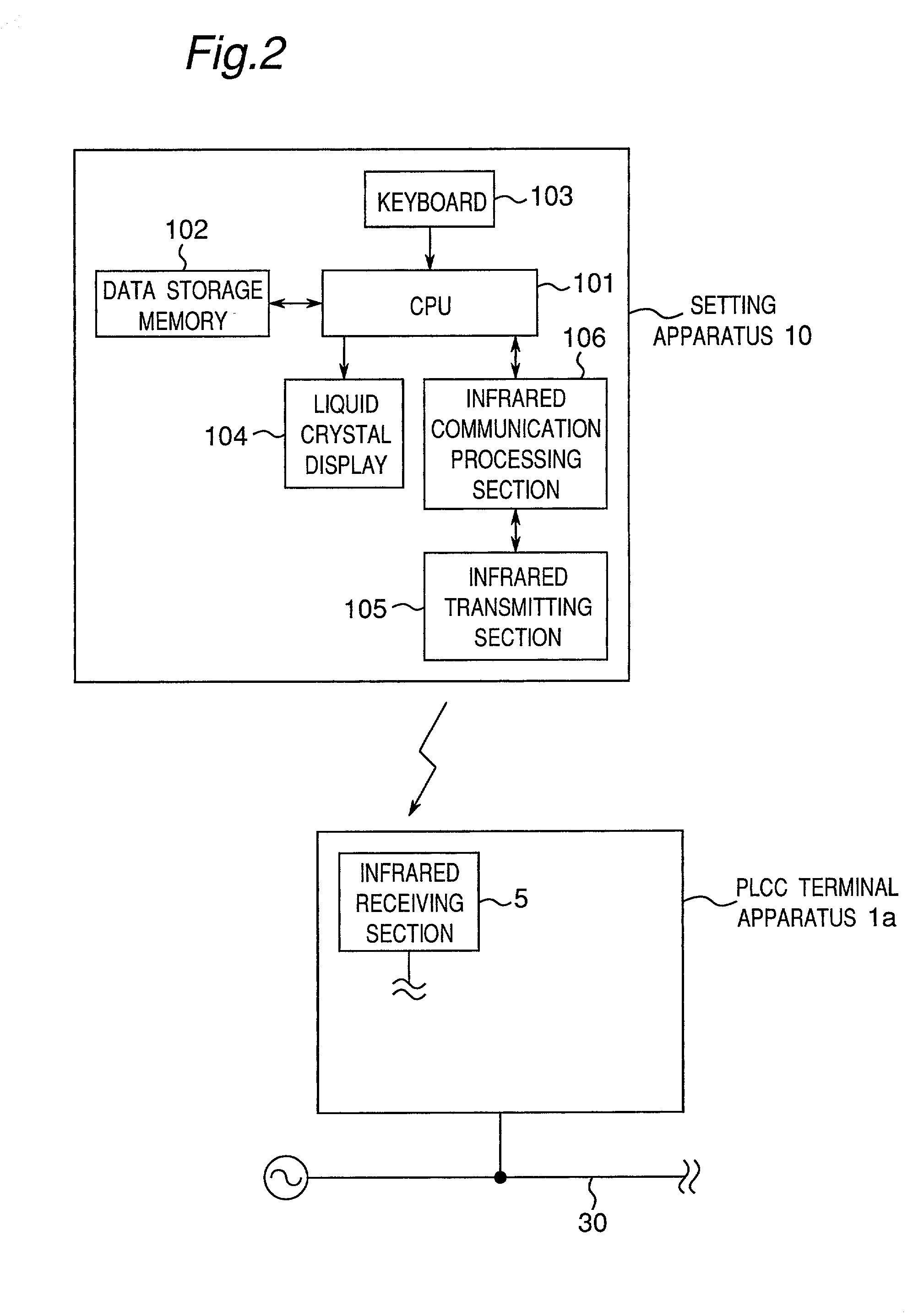
[0124] FIG. 6 is a schematic block diagram showing a detailed configuration of a setting apparatus 10a of a modified preferred embodiment. As compared with the setting apparatus 10 shown in FIG. 2, the setting apparatus 10a of the present modified preferred embodiment is characterized in further comprising the followings:

[0125] (a) a serial communication interface which is connected with a personal computer 40 for inputting interlocking operation information among the PLCC terminal apparatuses and program data for program operation; and

[0126] (b) a removable PC card memory 108 for storing setting information including attribute information, interlocking operation information, the program data or the like.

[0127] Referring to FIG. 6, the setting apparatus 10a includes the serial communication interface such as an RS-232C interface, a USB interface or the like, which is provided as data input section from the personal computer 40. In this case, data of sett...

second preferred embodiment

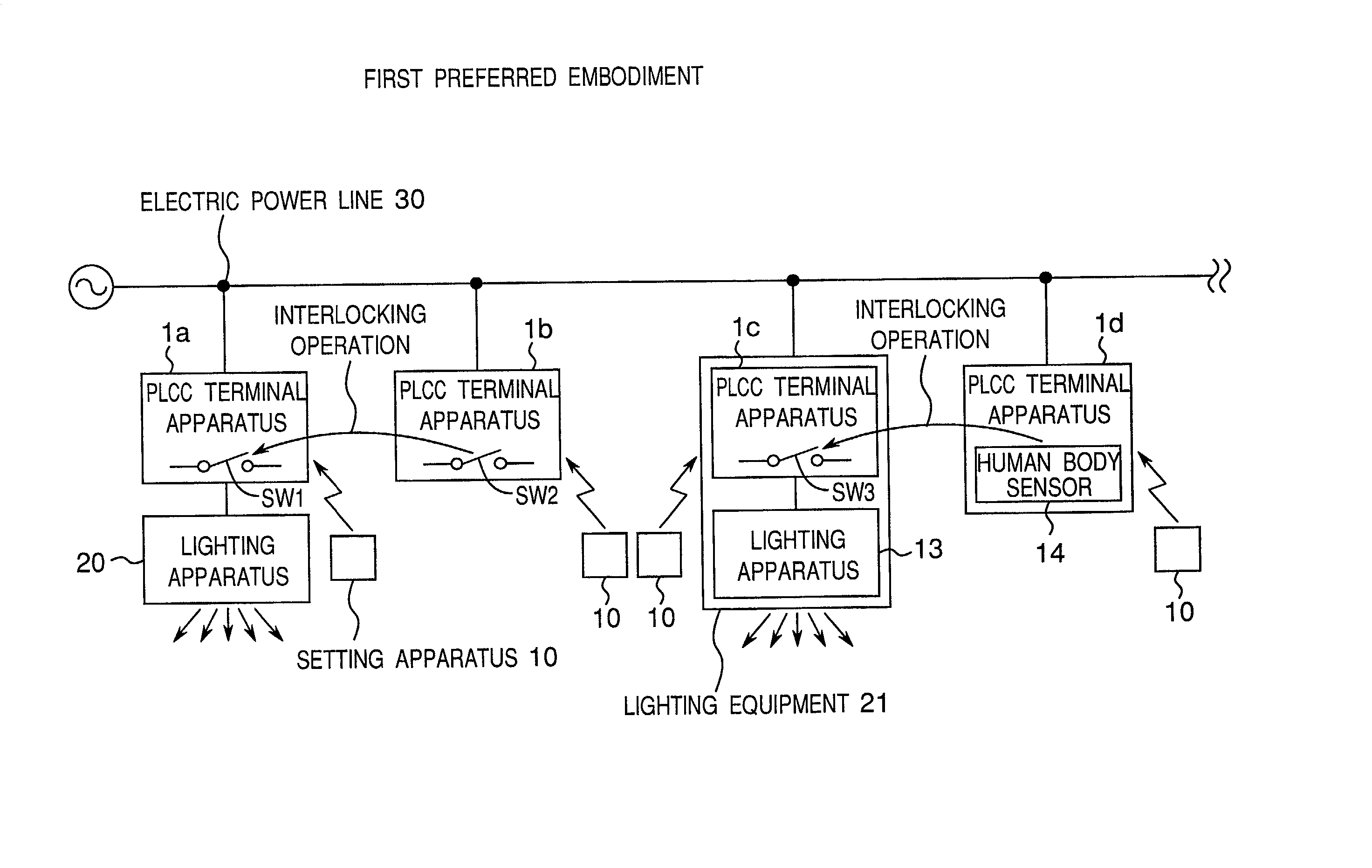
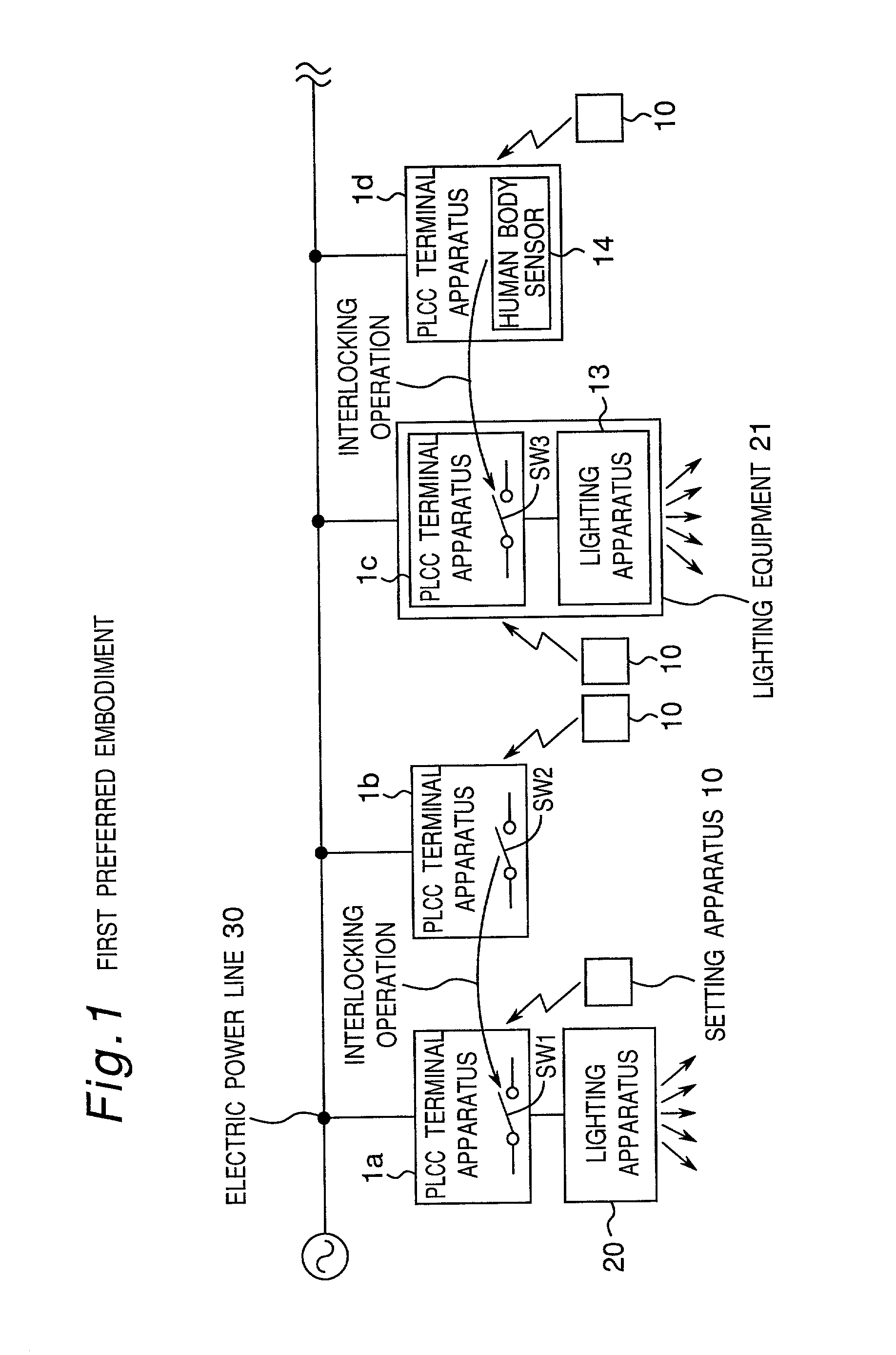
[0132] FIG. 8 is a schematic block diagram showing a configuration of an electric power line carrier communication system according to a second preferred embodiment of the present invention. As compared with the communication system of the first preferred embodiment shown in FIG. 1, the communication system of the second preferred embodiment is characterized in the followings:

[0133] (a) in order to specify the position of each of the PLCC terminal apparatuses 301a, 301b, 301c and 301d, namely, to specify the relationship between terminal information data which is listed in a terminal table and each of the PLCC terminal apparatuses 301a, 301b, 301c and 301d which is practically installed, an infrared signal transmitter 310 transmits an infrared signal toward each of the PLCC terminal apparatuses 301a, 301b, 301c and 301d, and then, each of the PLCC terminal apparatuses 301a, 301b, 301c and 301d transmits a detection signal to the PLCC setting apparatus 200 in response to the infrared...

third preferred embodiment

[0146] FIG. 12 is a schematic block diagram showing a configuration of an electric power line carrier communication system according to a third preferred embodiment of the present invention. As compared with the second preferred embodiment, the communication system of the third preferred embodiment is characterized in the followings:

[0147] (a) there is provided no infrared signal transmitter 310;

[0148] (b) a PLCC terminal apparatus 401a having an operating switch SW11 for inputting a predetermined ON / OFF input pattern (referred to as an ON / OFF pattern hereinafter) to specify the same PLCC terminal apparatus 401a is provided in stead of the PLCC terminal apparatus 301a having the infrared receiving section 5;

[0149] (c) a PLCC terminal apparatus 401b having an operating switch SW12 for inputting a predetermined ON / OFF pattern to specify the same PLCC terminal apparatus 401b is provided in stead of the PLCC terminal apparatus 301b having the infrared receiving section 5;

[0150] (d) a PL...


PUM


Abstract

A setting apparatus and a setting method are provided for setting setting information including attribute information and interlocking operation information into an electric power line carrier communication terminal apparatus equipped with an electric power line carrier communication section for performing electric power line carrier communication through an electric power line of a commercial electric power source. The setting information is previously stored in a data storage memory, and an infrared transmitting section transmits the setting information stored in the data storage memory, directly to the electric power line carrier communication terminal apparatus using an infrared communication method.

Description

[0001] 1. FIELD OF THE INVENTION[0002] The present invention relates to a setting apparatus and a setting method each for setting setting information in an electric power line carrier communication terminal apparatus, and in particular, to a setting apparatus and a setting method each for setting setting information including attribute information and interlocking operation information into an electric power line carrier communication terminal apparatus equipped with electric power line carrier communication means for performing electric power line carrier communication through an electric power line of a commercial electric power source.[0003] 2. DESCRIPTION OF THE RELATED ART[0004] Conventionally, there have been available electric power line carrier communication terminal apparatuses which are of three kinds of followings installed in a distributed manner in a building such as a house or the like:[0005] (a) a first electric power line carrier communication terminal apparatus, pro...

Claims


Application Information

Patent Timeline
Patent Type & Authority Applications(United States)
IPC IPC(8): H04B3/54H04L12/28H04Q9/00H05B37/02
CPCG05B2219/25188G05B2219/25192H04B3/54H04B2203/5441H04L12/2803H05B37/0263H04L12/66H04L2012/2843H04L2012/285H05B37/0245H04L12/2807H05B47/185H05B47/175
Inventor OKADA, YUKIOKUNIYOSHI, KENJIKOMODA, YOSHIYUKI
Owner MATSUSHITA ELECTRIC WORKS LTD
Why Eureka
Try Eureka