
Vehicle-mounting steering switch

a steering switch and vehicle-mounted technology, applied in mechanical equipment, gearing control, transportation and packaging, etc., can solve the problems of significant restriction of design freedom, largely restricted space for installing manipulating knobs,

Inactive Publication Date: 2002-06-06
ALPS ALPINE CO LTD
View PDF0 Cites 13 Cited by
  • Summary
  • Abstract
  • Description
  • Claims
  • Application Information

AI Technical Summary

Benefits of technology

[0011] In the vehicle-mounting steering switch having such a constitution, when a driver pushes one manipulating knob which is protruded into the space defined between the spokes and the ring of the steering wheel toward the depth side or pulls such a manipulating knob in the front direction with his finger, two different kinds of electric signals are selectively outputted from the output changeover means in response to the rotating direction of the manipulating knob. Accordingly, two different controls can be performed with the push / pull manipulation of one manipulating knob so that the operability can be enhanced and the installation space can be reduced.
[0012] In the abovementioned constitution, it is preferable that the output changeover means is constituted of a first contact member which is mounted on the supporting member and a second contact member which is mounted on the manipulating knob and relative positions of these first and second contact members are changed in response to the rotating direction of the manipulating knob. By distributing the constituent members of the output changeover means to the support member and the manipulating knob in this manner, the vehicle-mounting steering switch can be miniaturized. In this case, a circuit board on which a conductive pattern such as a resistance pattern and a contact pattern is formed is preferably used as the first contact member and a sliding element which is brought into slide contact with the conductive pattern is preferably used as the second contact member. Due to such a constitution, two kinds of electric signals can be outputted from the circuit board which is mounted on the fixed-side supporting member so that the pulling-around of the signals is facilitated.
[0014] In the vehicle-mounting steering switch having such a constitution, when a driver pushes one manipulating knob which is protruded into the space defined between the spokes and the ring of the steering wheel toward the depth side or pulls such a manipulating knob toward the front direction with his finger, two different kinds of electric signals are selectively outputted from the output changeover means in response to the rotational direction of the manipulating knob. Then, when the abovementioned pushing force or pulling force applied to the manipulating knob is removed, the push element is shifted from the crest to the valley of the cam face upon receiving the biasing force of the resilient member so that the manipulating knob is held at the rotationally neutral position in a stable manner. Accordingly, the driver can perform two different controls by performing with his finger the push / pull manipulation of one manipulating knob which is held at the rotationally neutral position. Furthermore, by releasing fingers from the manipulating knob, the manipulating knob automatically returns to the rotationally neutral position so that the operability is enhanced and, at the same time, the space for installing the manipulating knob can be reduced.
[0015] In the abovementioned constitution, it is preferable that the cam face is formed on the support member and the push element and the resilient member are held by the manipulating knob. In this case, by accommodating the push element and the resilient member in a holder and by inserting and fixedly securing a portion of the holder in a recess formed in the manipulating knob, the push element, the resilient member and the holder can be simply assembled into the manipulating knob so that the operability of assembling is enhanced.
[0017] In the vehicle-mounting steering switch having such a constitution, when a driver pushes one manipulating knob which is protruded into the space defined between the spokes and the ring of the steering wheel toward the depth side or pulls such a manipulating knob toward the front direction with his finger, two different kinds of electric signals are selectively outputted from the output changeover means in response to the rotational direction of the manipulating knob. Then, at a point of time that the stopper protrusion is brought into contact with the inner wall of the hollow, the further rotation of the manipulating knob is restricted. Accordingly, the driver can perform two different controls by performing the push / pull manipulation of one manipulating knob with his finger. Furthermore, even when an excessive force is applied to the manipulating knob during such a manipulation, the force is received by the stopper protrusion in a stable manner and hence, the operability can be enhanced and the space for installing the manipulating knob can be reduced.
[0018] In the abovementioned constitution, it is preferable that the stopper protrusion is mounted on a fixed-side support member and the hollow is formed on the movable-side manipulating knob. Due to such a constitution, by making effective use of the inner space of the manipulating knob, a stopper mechanism having a compact shape and high strength can be realized. In this case, by increasing a thickness of the inner wall of the hollow at a position with which the stopper protrusion is brought into contact compared to other peripheral portions, the strength of the stopper can be further enhanced.

Problems solved by technology

However, it is usually necessary to ensure a space for installing a horn switch, an airbag and the like in the pad of the steering wheel so that there arises a problem that the space for installing the manipulating knobs is largely restricted.
Such an arrangement which arranges a large number of manipulating knobs in the limited space of the steering wheel also gives rise to a problem that the degree of freedom of design is significantly restricted.

Method used


Image

  • Vehicle-mounting steering switch
  • Vehicle-mounting steering switch
  • Vehicle-mounting steering switch

Examples


Embodiment Construction

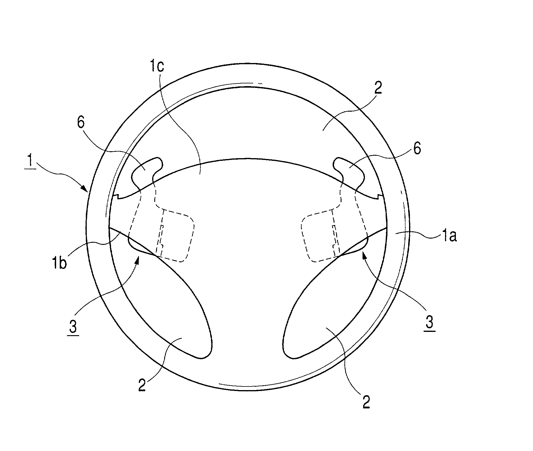
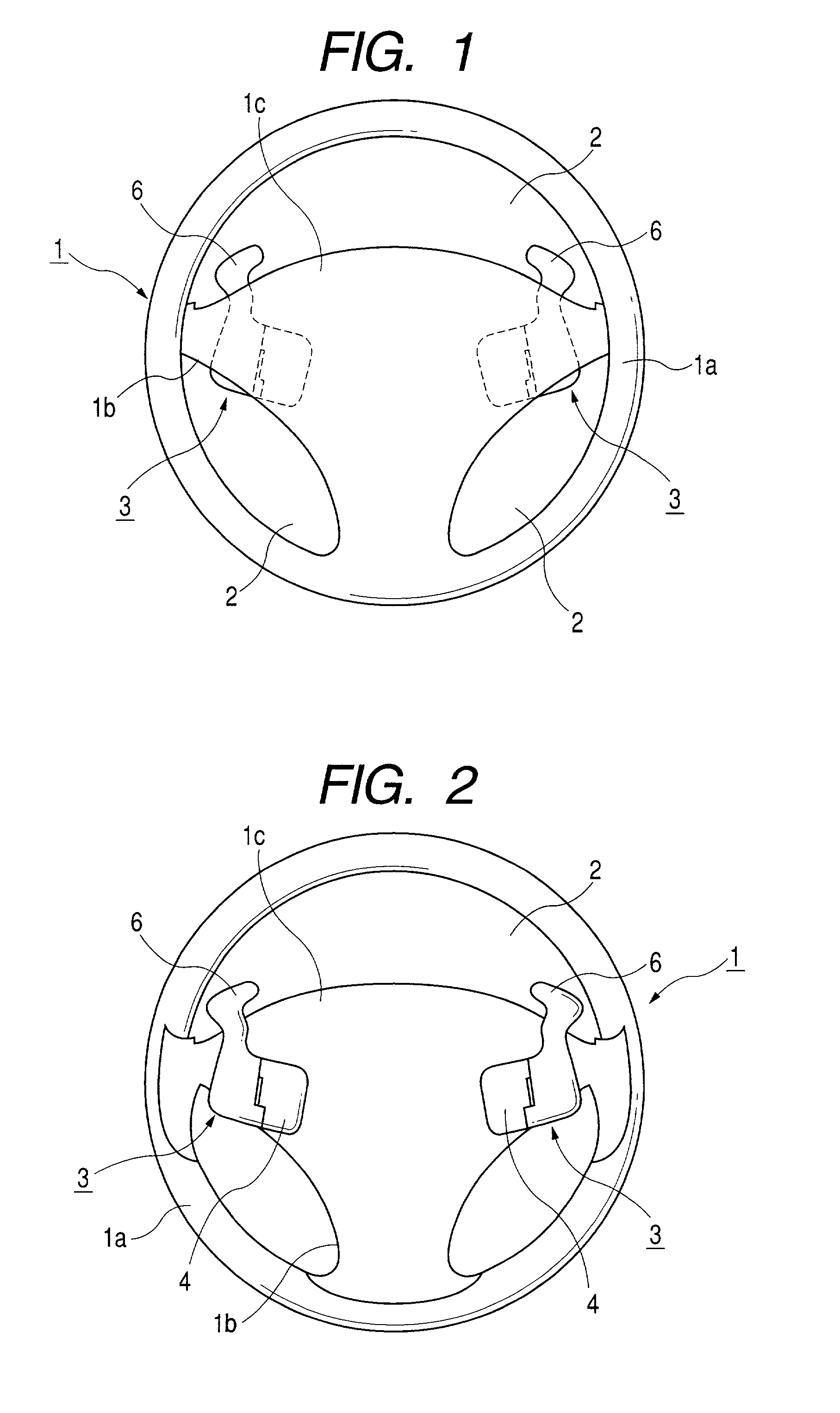
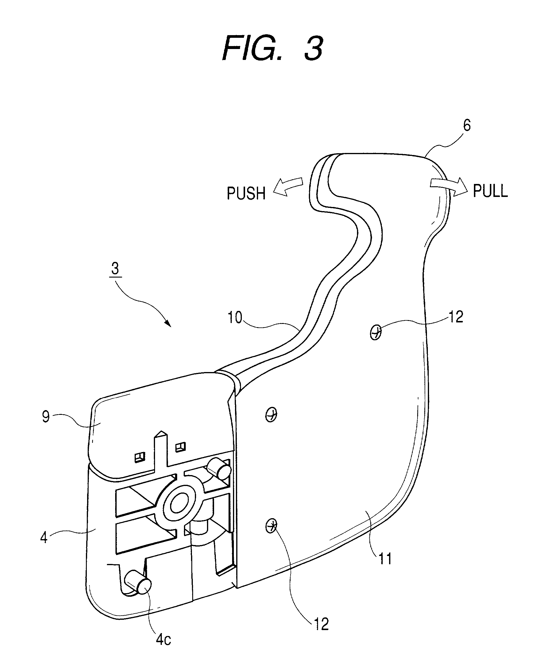
[0026] To explain embodiments of the present invention in conjunction with attached drawings, FIG. 1 is a front view of a steering wheel to which a vehicle-mounting steering switch according to an embodiment of the present invention is attached, FIG. 2 is a rear view of the steering wheel, FIG. 3 is a perspective view of the vehicle-mounting steering switch, FIG. 4 is an exploded perspective view of the vehicle-mounting steering switch, FIG. 5 is an explanatory view showing a self return mechanism of the vehicle-mounting steering switch, and FIG. 6 is an explanatory view showing a stopper mechanism of the vehicle-mounting steering switch and the changeover operation of contacts.

[0027] As shown in FIG. 1 and FIG. 2, a steering wheel 1 is substantially constituted of an annular ring 1a thereof, spokes 1b which are extended from an inner side of the ring 1a toward the center of the ring 1a and a pad 1c which substantially covers the whole of the spokes 1b. A plurality of (for example, ...


PUM


Abstract

The present invention discloses a vehicle-mounting steering switch which exhibits excellent operability and requires just a small installation space. A vehicle-mounting steering switch includes a manipulating knob which is rotatably and pivotally supported on a support member. The support member is fixedly secured to a rear surface of a pad of the steering wheel and, at the same time, the manipulating knob is protruded into the inside of a space defined between a ring and the pad. A circuit board which is provided with a pair of resistance patterns is mounted on the support member, while a sliding element which is slidable on the circuit board is mounted on the manipulating knob. When a driver performs push or pull manipulation of the manipulating knob with his finger, a relative position of the circuit board and the sliding element is changed so that two kinds of ON signals are outputted. In response to these ON signals, it becomes possible to perform shift-up or shift-down of transmission gears in the midst of cruising in a drive range.

Description

[0001] 1. Field of the Invention[0002] The present invention relates to a vehicle-mounting steering switch which is attached to a steering wheel of an automobile and is served for manipulating various equipment such as an automatic transmission.[0003] 2. Description of the Prior Art[0004] Conventionally, there has been known a technique in which a plurality of steering switches are mounted at an arbitrary position of a steering wheel and when a driver selectively manipulates these steering switches, the transmission gears are shifted up or down manually in the midst of travelling within a drive range, for example.[0005] As a conventional example of such a vehicle-mounting steering switch, there has been proposed a vehicle-mounting steering switch in which a plurality of manipulating knobs are arranged at a front surface or both front and back surfaces of a pad extending toward the inside of a ring of the steering wheel and press switches are respectively housed in the inside of resp...

Claims


Application Information

Patent Timeline
IPC IPC(8): B60K20/06B60Q1/00B62D1/04
CPCB60K20/06B60Q1/0082F16H2059/0247H01H2021/225F16H2059/0239B62D1/046B62D1/04
Inventor AGETSUMA, NOBUAKI
Owner ALPS ALPINE CO LTD
Learn More