Electronic ballast with feed-forward control
- Summary
- Abstract
- Description
- Claims
- Application Information
AI Technical Summary
Benefits of technology
Problems solved by technology
Method used
Image
Examples
Embodiment Construction
)
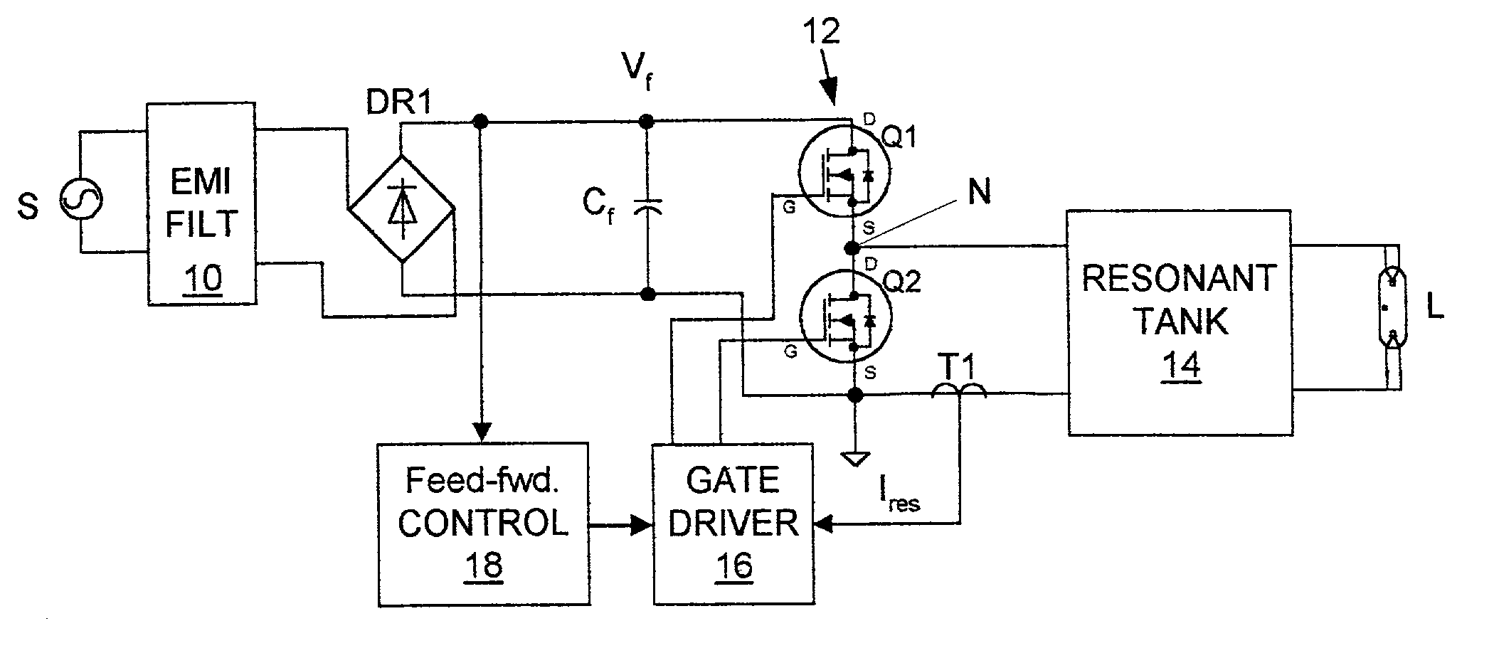
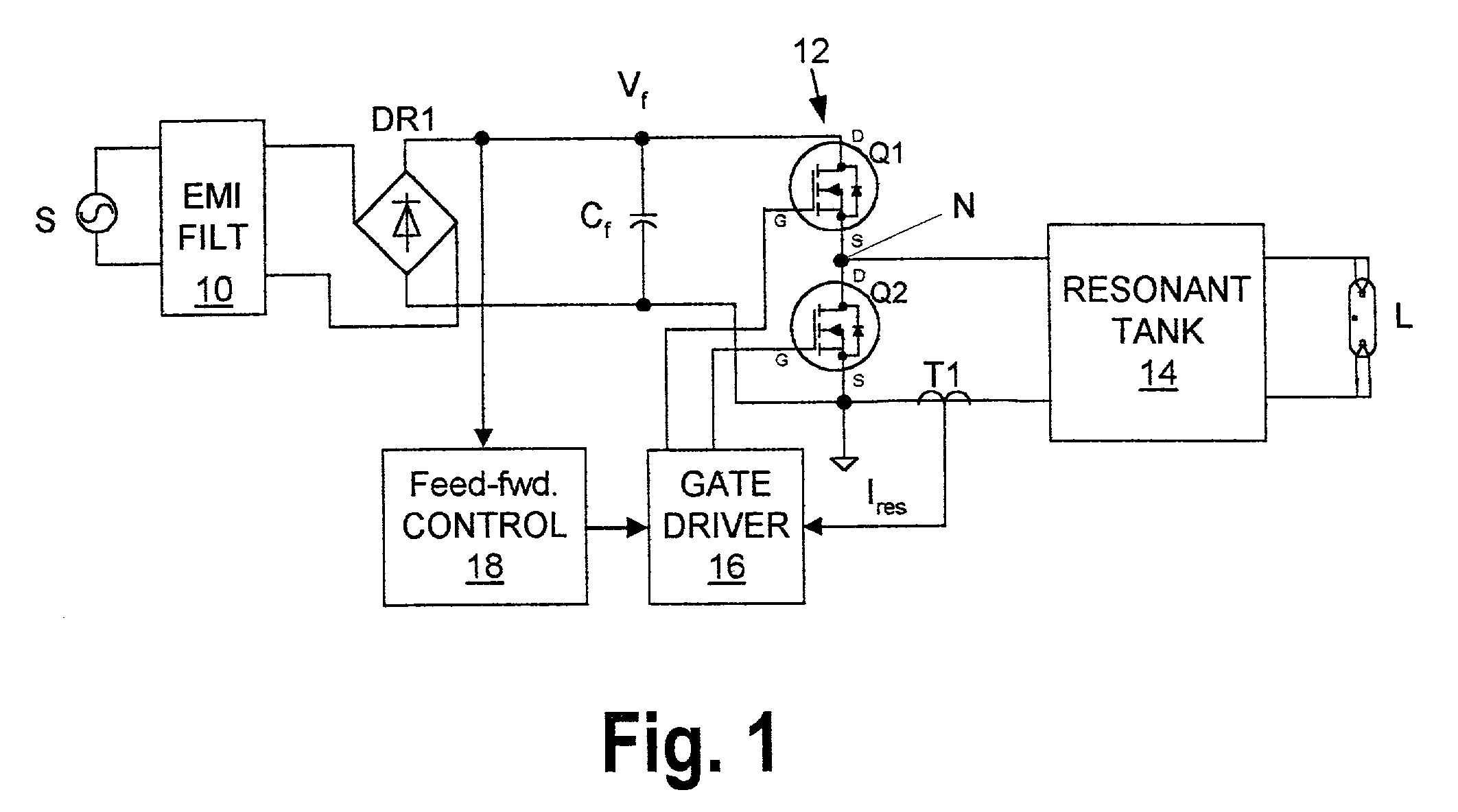
[0014] The exemplary system shown in FIG. 1 includes a source of AC power S, a discharge lamp L (e.g. a fluorescent lamp) and a ballast for controllably passing power to the lamp from the source S. The ballast includes an EMI filter 10, a bridge rectifier DR1, a line-filter capacitor C.sub.f, a half-bridge converter 12, a resonant tank 14, a current transformer T1, a gate driver circuit 16 and a feed-forward control circuit 18.
[0015] The EMI filter 10 serves to isolate the AC power source S from interference signals generated within the ballast (e.g. high-frequency switching signals generated by the converter 12).
[0016] The bridge rectifier DR1 and the filter capacitor C.sub.f convert the AC power from the source S to rectified, but unregulated, DC power having a varying DC voltage V.sub.f. Together, this rectifier and capacitor form a DC power source that is conventional except for its simplicity and the relatively small size of the filter capacitor that is possible because of the...
PUM
 Abstract
Description
Claims
Application Information
 - R&D
- Intellectual Property
- Life Sciences
- Materials
- Tech Scout
- Unparalleled Data Quality
- Higher Quality Content
- 60% Fewer Hallucinations
Browse by: Latest US Patents, China's latest patents, Technical Efficacy Thesaurus, Application Domain, Technology Topic, Popular Technical Reports.
© 2025 PatSnap. All rights reserved.Legal|Privacy policy|Modern Slavery Act Transparency Statement|Sitemap|About US| Contact US: help@patsnap.com


