
Pressurized screen and process for removing contaminants from a fibrous paper suspension containing contaminants

Inactive Publication Date: 2002-06-13
VOITH PATENT GMBH
View PDF5 Cites 17 Cited by
  • Summary
  • Abstract
  • Description
  • Claims
  • Application Information

AI Technical Summary

Benefits of technology

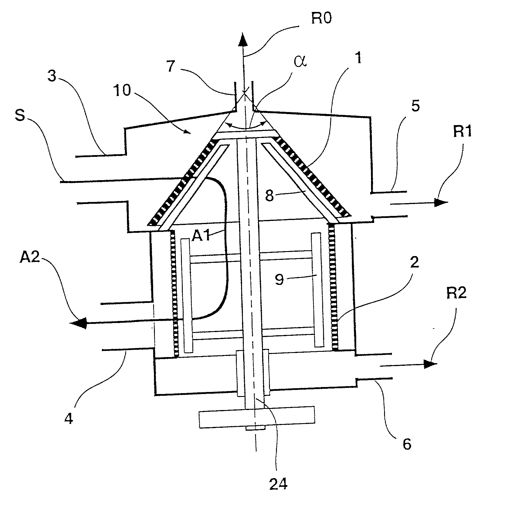
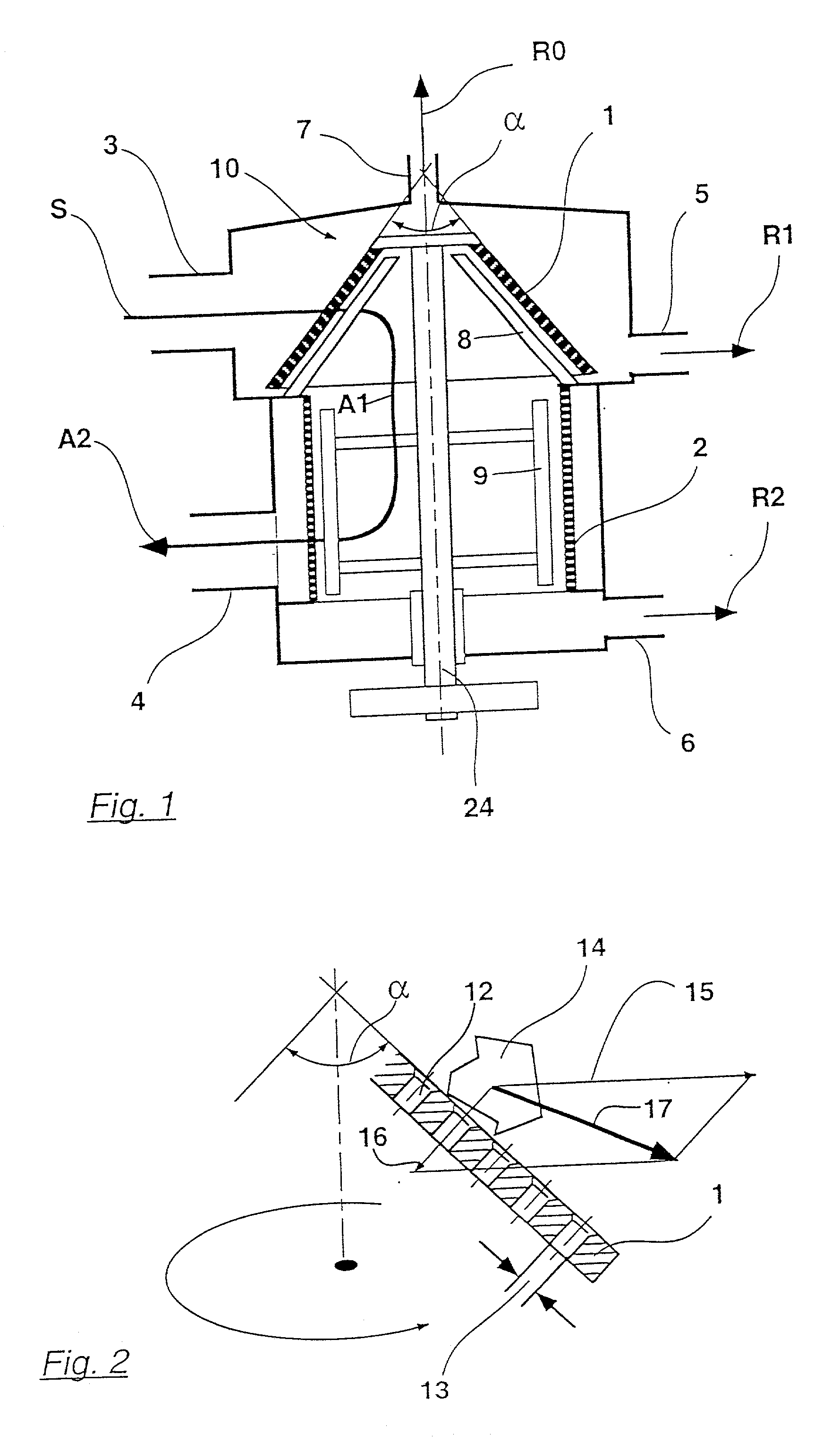
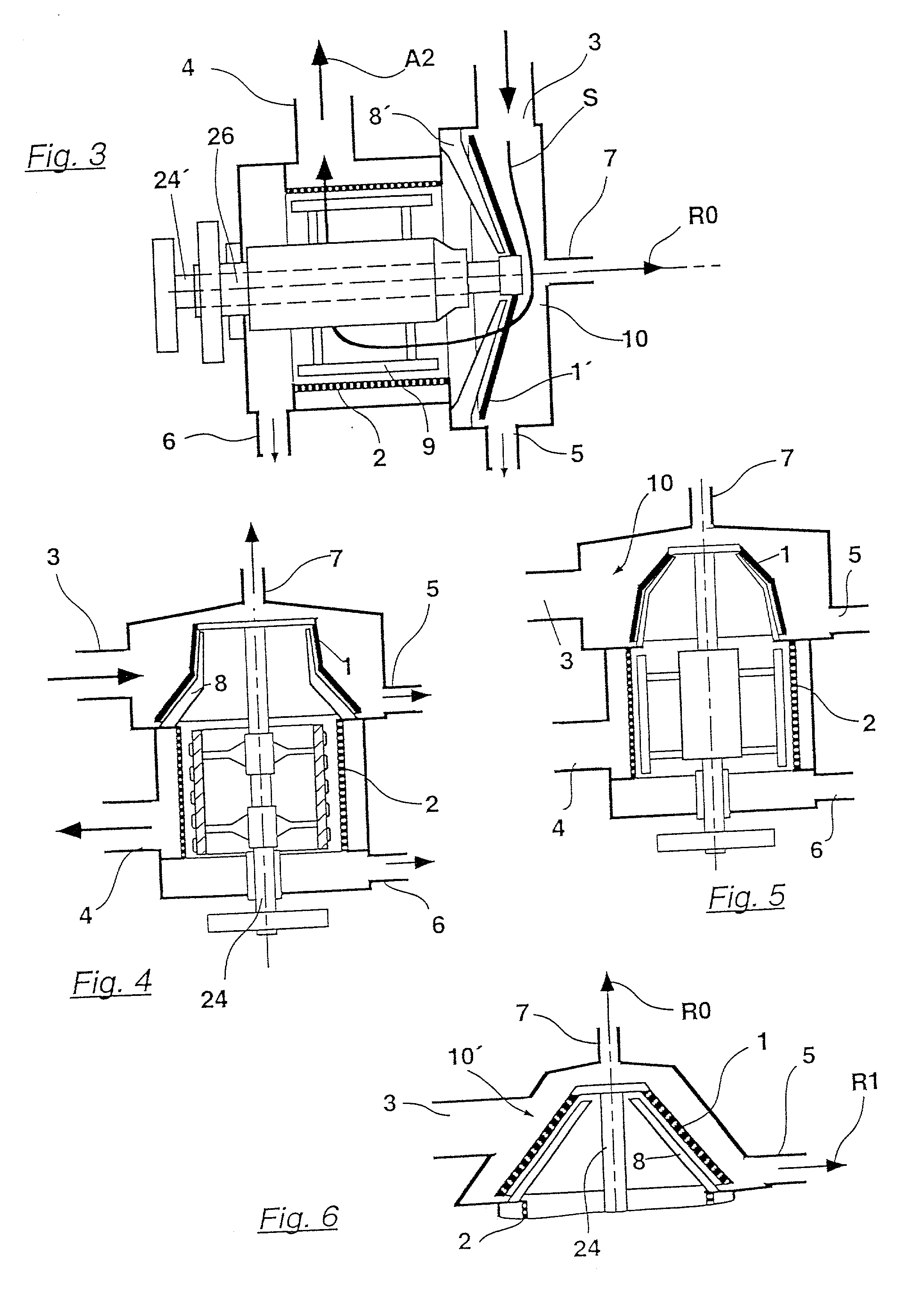
[0014] After entering the pressurized screen according to the invention, the suspension encounters the intake side of the first screen element. Its rotation creates a centrifugal force with which the contaminants are spun from the surface of this screen element, provided they have a higher specific gravity than the suspension surrounding them. Thus not only the tractive forces created due to the pressure difference, but also centrifugal forces act on the solid particles located near the screen intake. The more the longitudinal direction of the screen opening is oriented radially (instead of axially), the stronger the free centrifugal effect and the lower the danger of the particles being caught in the openings. Heavy particles that are rejected at the screen element according to the specification, leave its intake area relatively quickly and are then removed from the housing through the coarse reject outlet. They may possibly also carry with them light contaminants rejected because of their size, particularly plastic foils. The screen is not only less at risk of wear, but it is also not so easily clogged by wire pieces, splinters of glass and small stones.
[0015] The centrifugal effect naturally depends on the speeds and the radius at the place in question. The particular advantage of the invention lies in the fact that the first screen element is constructed conically at least in part. A conical form combines the advantages of a large screen surface with sufficient centrifugal effect from the screen area.
[0016] Through the combination according to the invention of the two screen elements that work differently in one housing, a compact machine is created that works reliably even with heavily contaminated liquids. Another advantage is the possibility of being able to provide the first screen element and the scrapers for the second screen element with a common drive.
[0025] A centrally aligned light reject outlet may be coupled to the housing. The light reject outlet can be located in a region of the first screen element. The first screen element may be arranged in the housing to form an intake chamber outside of the first screen element, and the light reject outlet may be located in the intake chamber. Further, the light reject outlet can include a closable valve that automatically opens for a short time at intervals. A rotor can be arranged to drive the first screen element, such that no mounting structure is positioned between the first screen element and the light reject outlet.

Problems solved by technology

However, in certain cases this known screen has the disadvantage that a high degree of wear occurs, particularly in the area of the flat primary screen, and the coarse impurities can lead to breakdowns.
However, these devices are unfavorable in many applications.
A cylindrical screen has the disadvantage in particular that the oblong impurities with a tendency to spin or wind can easily stick to such a screen and then become firmly fastened as a result of the rotation.
However, it has only a small screen surface, which is disadvantageous.
If waste paper is brought into the pulper or cleaning drum in suspension, for instance, it often has a contaminant content of more than 2% of the solids.
They may possibly also carry with them light contaminants rejected because of their size, particularly plastic foils.

Method used


Image

  • Pressurized screen and process for removing contaminants from a fibrous paper suspension containing contaminants
  • Pressurized screen and process for removing contaminants from a fibrous paper suspension containing contaminants
  • Pressurized screen and process for removing contaminants from a fibrous paper suspension containing contaminants

Examples


Embodiment Construction

[0050] The particulars shown herein are by way of example and for purposes of illustrative discussion of the embodiments of the present invention only and are presented in the cause of providing what is believed to be the most useful and readily understood description of the principles and conceptual aspects of the present invention. In this regard, no attempt is made to show structural details of the present invention in more detail than is necessary for the fundamental understanding of the present invention, the description taken with the drawings making apparent to those skilled in the art how the several forms of the present invention may be embodied in practice.

[0051] The present invention is directed to a "pressurized screen," which is so named because these devices are closed and because the throughput occurs from a pressure difference between an intake and a pass through (accepted stock). Moreover, there are other screen devices that are open at the top, in which case, they ...


PUM

PropertyMeasurementUnit
Angleaaaaaaaaaa
Angleaaaaaaaaaa
Diameteraaaaaaaaaa

Abstract

Pressurized screen to remove contaminants from a contaminant-containing fibrous paper suspension. Pressurized screen includes a housing, a first screen element, essentially axially symmetric and rotatably mounted within housing, and a second screen element, which is essentially axially symmetric. First and second screen elements are successively arranged in suspension flow direction. At least one intake, coupled to housing, supplies suspension to housing, and at least one accepts outlet, coupled to housing, conveys a part of suspension that passes through the second screen element out of housing. At least one coarse reject outlet is located within housing to remove a part of suspension not passing through first screen element, and at least one fine reject outlet is located within housing to remove a part of suspension not passing through second screen element. First screen element includes conical shape with opening angle (alpha) between about 10° and 170°.

Description

[0001] The present application claims priority under 35 U.S.C. .sctn. 119 of German Patent Application No. 100 60 822.1, filed on Dec. 7, 2000, the disclosure of which is expressly incorporated by reference herein in its entirety.[0002] 1. Field of the Invention[0003] The invention relates to a pressurized screen to remove contaminants from a contaminant-containing fibrous paper suspension with a vertical housing that contains at least two mainly axially symmetrical screen elements that are arranged so that the fibrous suspension fed through at least one intake into the housing can flow through them in succession. The upstream first screen element can be rotated and is mounted axially outside and above the chamber in which the second screen element is located. A part of the fibrous paper suspension that has passed through the second screen element is channeled out of the housing through at least one accepts outlet. The housing further includes at least one coarse reject outlet for t...

Claims


Application Information

Patent Timeline
IPC IPC(8): D21D5/02D21D5/06
CPCD21D5/02D21D5/06D21D5/026
Inventor RIENECKER, REIMUNDSCHWEISS, PETER
Owner VOITH PATENT GMBH
Learn More