

Heat transfer pipe for refrigerant mixture
a technology of refrigerant mixture and heat transfer pipe, which is applied in the direction of refrigeration components, refrigeration machines, light and heating apparatus, etc., can solve the problem that it has not been conventionally known which type of internal configuration is most efficien
- Summary
- Abstract
- Description
- Claims
- Application Information
AI Technical Summary
Benefits of technology
Problems solved by technology
Method used
Image

Examples
first embodiment
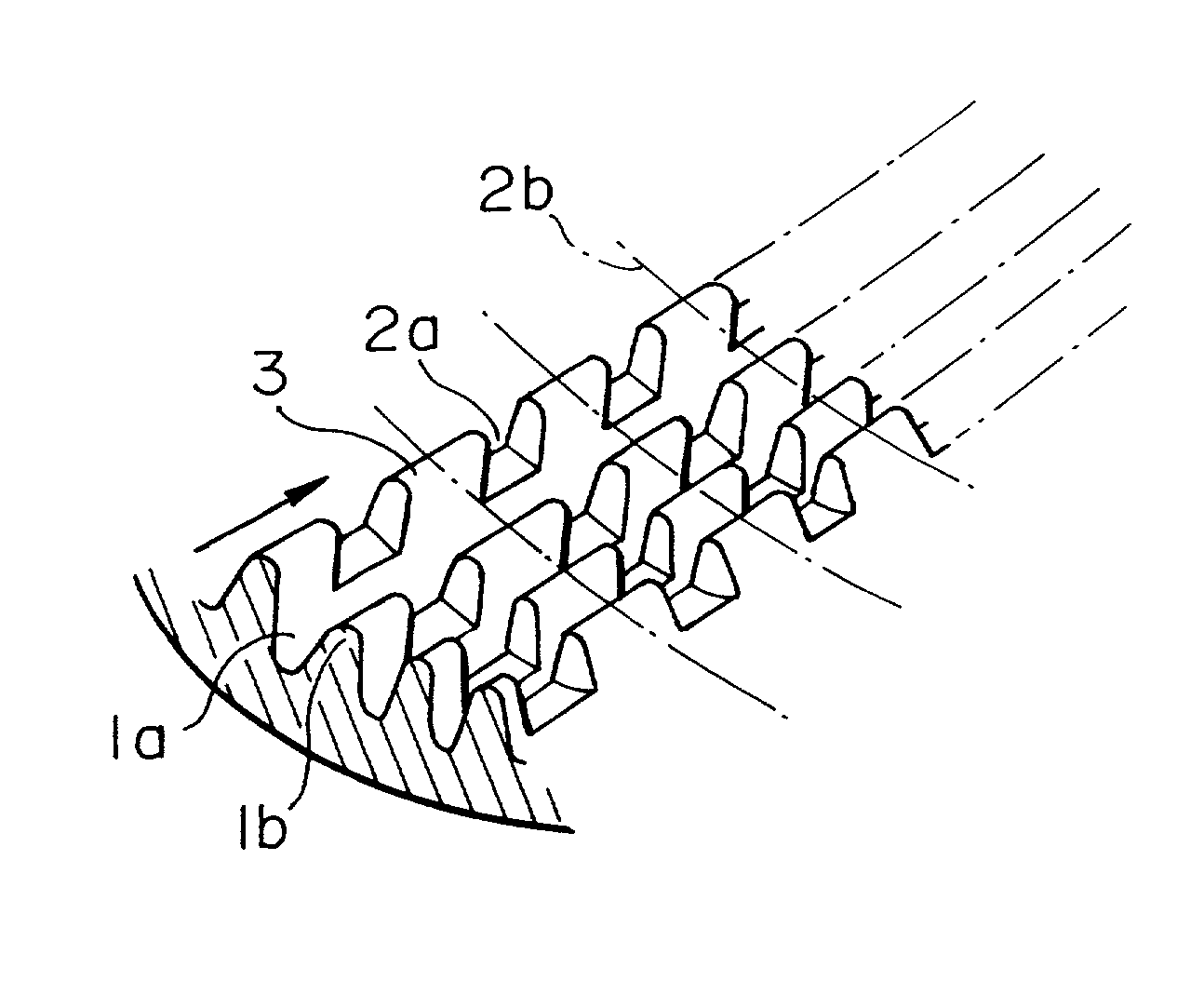
[0037] It is effective to divide the concentration boundary layers 5 into sections to improve the reduction of the condensation heat transfer coefficient in the refrigerant mixture which is a problem of prior art. To cope with this problem, this application proposes a pipe with cross grooves. As shown in a heat transfer pipe according to the present invention of FIG. 1, the pipe with cross grooves has main grooves 1a and auxiliary grooves 2a intersecting the main grooves 1a, both of them being formed on the inner surface of the pipe and ridges 1b formed by the provision of the main grooves 1a are divided into sections by the formation of the auxiliary grooves 2a intersecting the main grooves 1a to thereby form three-dimensional ribs 3. Each of the ribs 3 has a length longer than the width thereof as well as each of the auxiliary grooves has a width made smaller than the length of the ribs and the width of each of the main grooves so as to increase an amount of flow of the refrigeran...
second embodiment
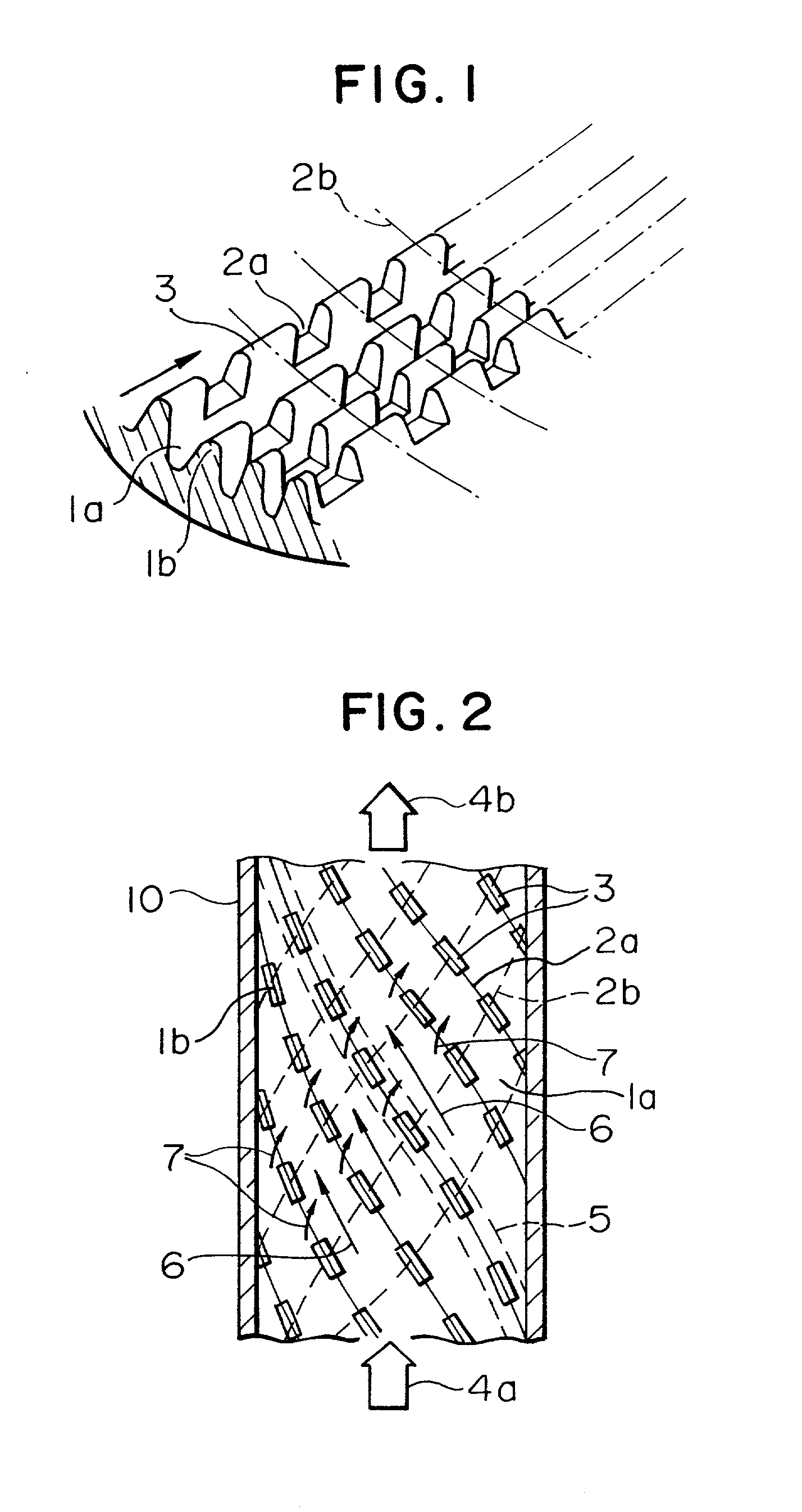
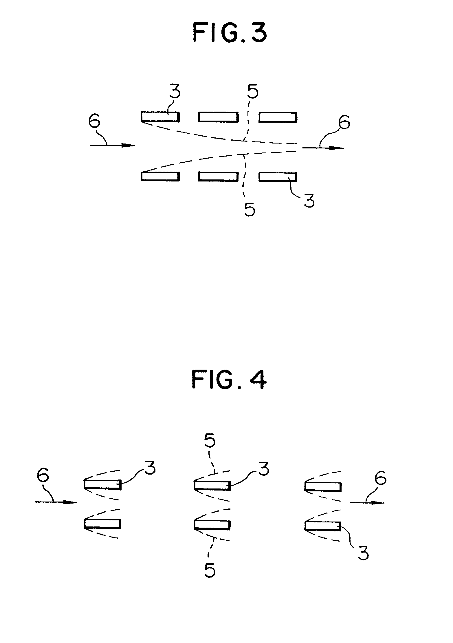
[0042] A second embodiment according to the present invention will be described with reference to FIG. 5 and FIG. 6. FIG. 6 is a view showing concentration boundary layers between the grooves of a pipe with cross grooves of this embodiment. As apparent from FIG. 6, auxiliary grooves 2b are disposed in parallel with a pipe axis. A refrigerant flowing in the vicinity of the center of the heat transfer pipe flows in the direction from a refrigerant inlet 4a to a refrigerant outlet 4b this direction coincides with the direction of the pipe axis. Consequently, the refrigerant tends to flow in the direction of the pipe axis. The parallel arrangement of the auxiliary grooves 2b with the pipe axis increases an amount of the refrigerant flowing in the auxiliary grooves, so as to divide the concentration boundary layers formed in the direction 6 of main grooves 1a. Therefore, new concentration boundary layers 5 are formed from respective three-dimensional ribs 3, respectively as shown in FIG....
third embodiment
[0046] A third embodiment according to the present invention will be described with reference to FIG. 10 and FIG. 11. FIG. 10 is a view showing concentration boundary layers between the grooves in a pipe with the cross grooves of this embodiment.
[0047] As shown in FIG. 10, this embodiment is arranged such that burrs 3a, 3b as convex deformed members are provided with each of three-dimensional ribs to induce a refrigerant flow. The burr 3a at the extreme end of the three-dimensional rib 3 faces in a direction opposite to that of the burr 3b at the rear end thereof so as to bend the refrigerant flow 6 along main grooves in the direction 7 of auxiliary grooves. FIG. 11 is a longitudinal cross sectional view of the heat transfer pipe and shows how the refrigerant flow 6 along the main grooves is bent in the direction 7 of the auxiliary grooves by the burs 3a, 3b attached to the three-dimensional ribs 3.
[0048] Although the present invention is described with respect to an example of cond...
PUM
| Property | Measurement | Unit |
|---|---|---|
| angle | aaaaa | aaaaa |
| spiral angle β2 | aaaaa | aaaaa |
| spiral angle | aaaaa | aaaaa |
Abstract
Description
Claims
Application Information