
Pre-separator for inlets of cascade impactors

a technology of inlet separation and impactor, which is applied in the direction of separation process, centrifuge, instruments, etc., can solve the problems of skewing the size distribution, inefficiency, and aerodynamic size characterization, and achieves a wider flow rate range and low viscosity

Inactive Publication Date: 2002-06-13
MSP
View PDF0 Cites 11 Cited by
  • Summary
  • Abstract
  • Description
  • Claims
  • Application Information

AI Technical Summary

Benefits of technology

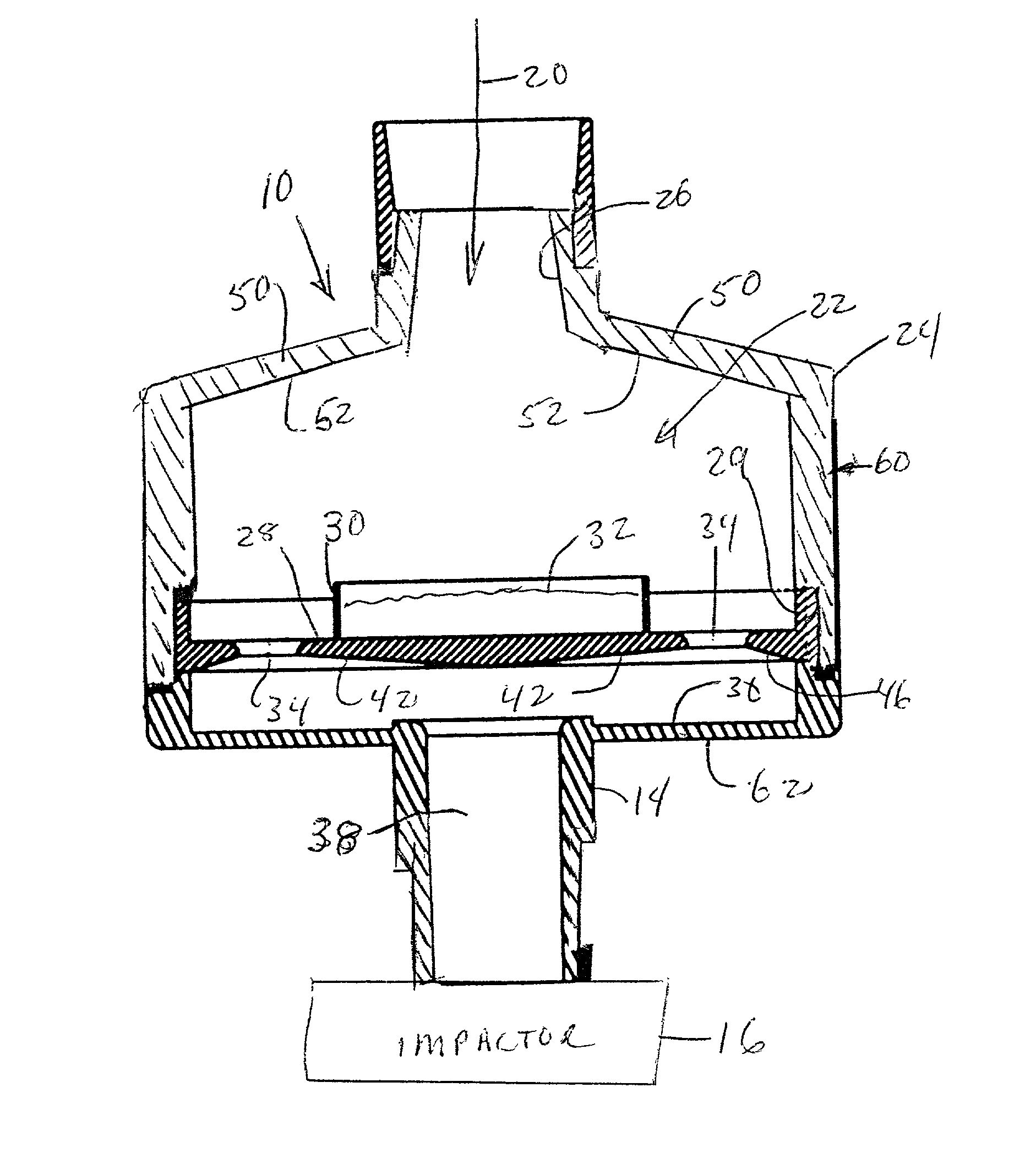
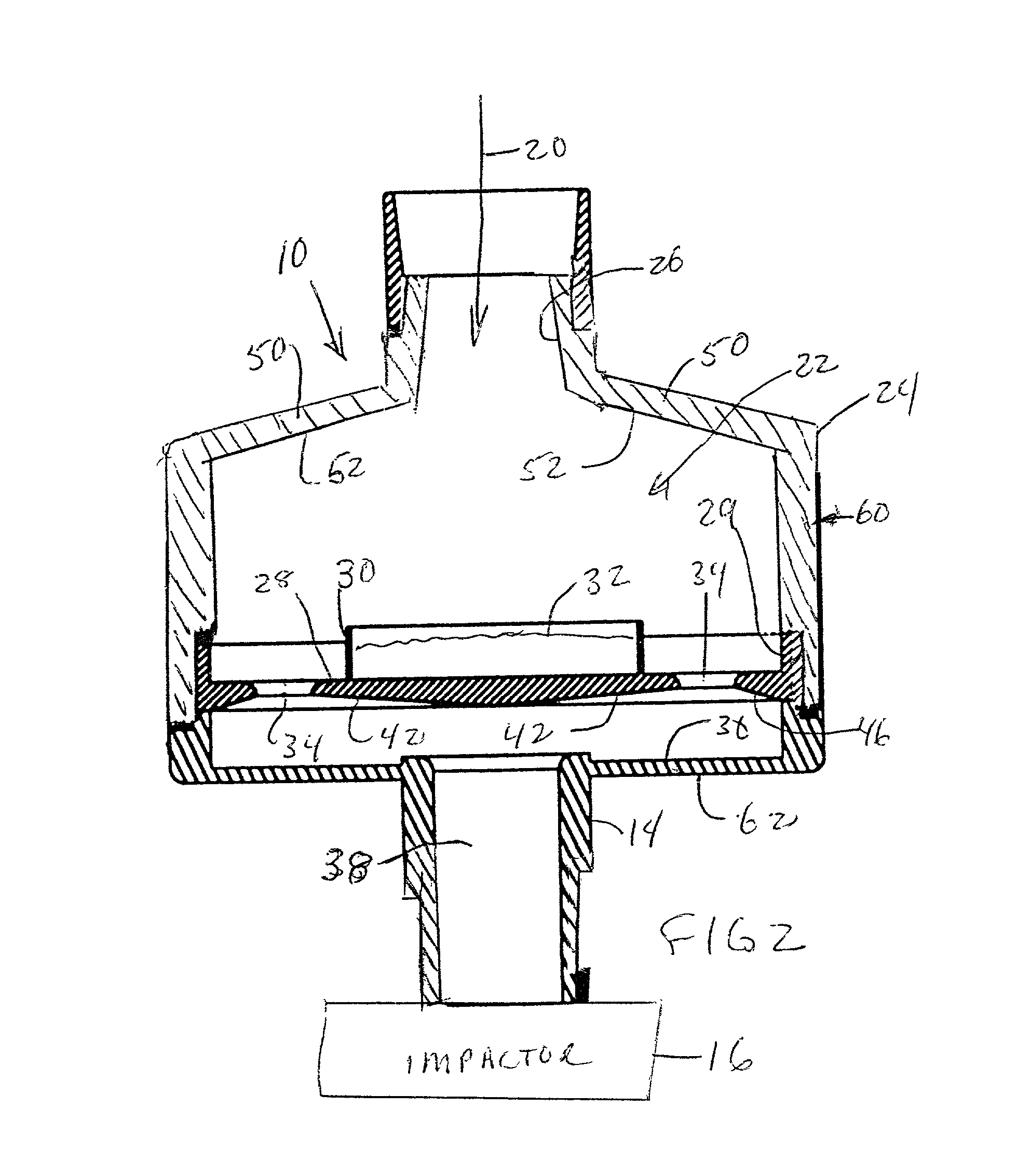
[0005] The present invention relates to a pre-separator for use with a cascade impactor that will separate large particles that are well outside of the range of interest in the impactor from the flow. The pre-separator utilizes a two stage separator arrangement, including one stage in which a low viscosity liquid is held in a cup, and against which the direct fluid input is impacted, and a second stage separator that provides for a flow through orifices or openings arranged annularly around the center cup. The two stage impaction in the pre-separator provides the ability to operate at a much wider flow rate range than with prior single stage pre-separators. A flow in the range of 30 to 100 liters per minute can be handled. This wide range of flows permits use of a single pre-separator for several impactor designs.

Problems solved by technology

The large material causes problems for the characterization of aerodynamic size via cascade impaction because the amount is so large that it overloads the holding capacity of the first stage of the impactor.
Consequently, large particles can bounce through to finer stages in the impactor, skewing the size distribution.
Furthermore, when the diluent particles are very much larger than the cut point of the first stage, they may not be captured efficiently even at low loading levels.

Method used


Image

  • Pre-separator for inlets of cascade impactors
  • Pre-separator for inlets of cascade impactors
  • Pre-separator for inlets of cascade impactors

Examples


Embodiment Construction

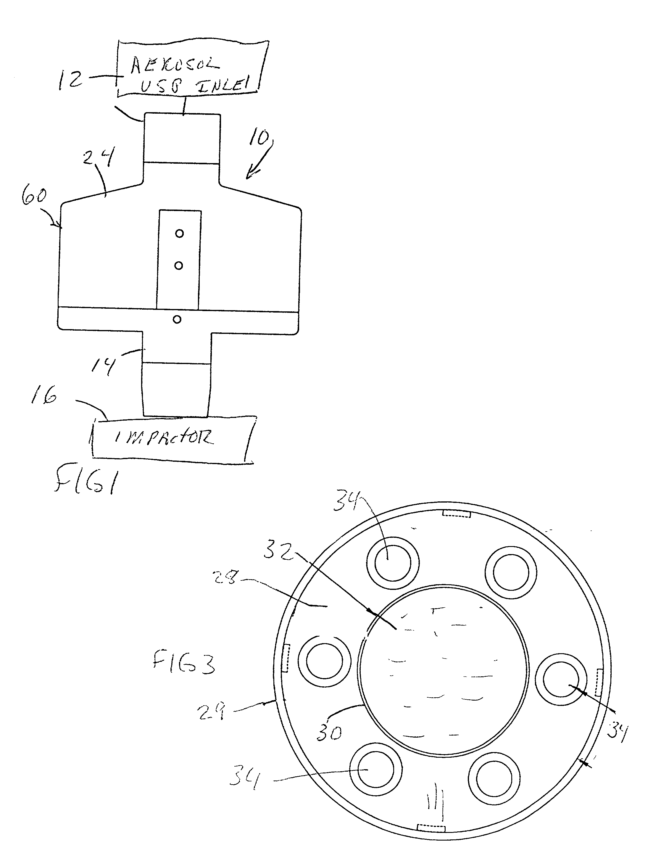
[0010] A pre-separator indicated generally at 10 is made to provide for a separation of large particles that are fed from a source of a gas carrying particles of interest, such as a dry powder inhaler, through a standard USP inlet indicated at 12. The pre-separator outlet comprising a fitting 14 is connected to a suitable cascade impactor 16 that is used for classifying particles carried through the inlet and the pre-separator into various size classifications.

[0011] In testing dry powder inhalers, very small amounts of active ingredients are carried in each dose, for example maybe 10's of milligrams of the active components. The total weight of particles that might be added, including the inert particles such as lactose, maybe 10's of micrograms so that only 0.1 percent of the particulate material is active material. The cascade impactor that is used is to accurately classify the small amount of active particles, the total weight which may be considered to be less than 1% of the to...


PUM

PropertyMeasurementUnit
sizeaaaaaaaaaa
areaaaaaaaaaaa
total weightaaaaaaaaaa

Abstract

A pre-separator for separating out large particles from a fluid flow has a housing forming an interior chamber with an inlet and an outlet, and a separator plate in the chamber between the inlet and outlet. The separator plate has a surface facing the inlet that is provided with a liquid carrying tank into which the flow is directed when it enters the interior chamber through the inlet. The separator plate has a series of nozzle openings therethrough adjacent its periphery to the outside of the tank. The nozzle openings adjacent the periphery of the separator plate overlie a surface of the housing adjacent the outlet. The pre-separator thus has two impaction stages that permit use across a wide range of flows. The separator plate and the housing have surfaces which are tapered so that liquid in the housing can be drained out when the housing is inverted.

Description

CROSS REFERENCE TO RELATED APPLICATIONS[0001] Reference is made to U.S. patent application Ser. No. 09 / 679,936, filed Oct. 5, 2000, for METHOD AND APPARATUS FOR CASCADE IMPACTOR TESTING OF INHALABLE DRUG THERAPIES RECOVERY FOR CHEMICAL ANALYSIS.BACKGROUND OF THE INVENTION[0002] In many instances, it is desired to have a pre-separator for aerosols that are being passed through a cascade impactor for classification, where the larger particles will be removed before entering the impactor.[0003] A cascade impactor utilizing a pre-separator is shown in U.S. patent application Ser. No. 09 / 679,963, filed Oct. 5, 2000. The type of impactor that may utilize a pre-separator is one which has very low volume of active material that is to be analyzed, with the active material incorporated in a flow of fluid that includes inert particles that are relatively large. The larger inert particles do not enter into the analysis, but are needed for carrying the active materials in a dispersed fashion thr...

Claims


Application Information

Patent Timeline
Patent Type & Authority Applications(United States)
IPC IPC(8): B01D45/08G01N15/02
CPCB01D45/08G01N2015/0261G01N15/0255
Inventor ROBERTS, DARYL L.MARPLE, VIRGIL A.
Owner MSP
Learn More