When distributing a distributed network of components within buildings, or between buildings, or within urban or suburban cores, it is often difficult to locate the physical location and actual installed components that comprise such distributed networks after the building or core is completely built, and field measurements must be conducted to determine suitability, quality, or proper performance of the "hidden" network.
In the case of distributed communications networks within buildings or campuses,
active components, such as
base station access points (for
wireless local area networks), base stations (for cellular or PCS systems), routers and switches (for wired or
wireless networks), cables and conduit that connect such active items, and individual user terminals (such as mainframe or portable computers, handheld devices,
Bluetooth devices, or other components (fixed or portable), that may be wired or wirelessly connected to a network) are used to send information from one place to another, and these are often difficult to physically detect.
While conceptually simple, the means of transmitting the data from some point A to some point B can be complicated and may widely vary in implementation.
The exact performance of a given data communication network is extremely difficult to predict or even measure because of this complexity.
Depending on particular number of users, network delays outside of the campus, or movement or settings of equipment within a facility or a large
area network, it is well known that there are a myriad of issues that may
impact the performance of a communications network and the channels that carry the information between users of such a network.
Pathchar is only limited by the network hardware in the links it measures.
This means that hidden links that do not transmit acknowledgements such as
Ethernet bridges cannot be measured individually by pathchar.
Furthermore, Smokoff et al do not provide any spatial information regarding the measurement or the measurement location.
Snider et al do not teach the concept of preprogramming, customizing, or recasting the text strings prior, during, or after measurements, nor do they teach the idea of graphical icons or textual strings being used to provide interpretation of measured information by an untrained or unskilled user.
In fact, Snider et al do not contemplate the use of graphical icons or text strings for the display or storeage of particular measured results.
Thus, Snider et al do not contemplate the use of graphical icons or textual strings by those with little technical knowledge, computer knowledge, or analytical ability.
Further, Snider does not contemplate spatially distributed measurements, or measurement cues, that allow a user to conduct a rapid survey of a spatially distributed network or group of objects by non-trained individuals.
Furthermore, Greenbaum et al do not contemplate the use of any spatial information regarding the measurement or the measurement location in their patent, nor do they contemplate the use of the diagram to drive the user to select a particular measurement type or location, or to be used by those with little technical knowledge, computer knowledge, or analytical ability.
In addition, Alexander does not consider the icon as providing any spatial information to the user as a cue for measurement position or location, nor does Alexander teach that the icon contains spatial information in the display of the measurement results.
Furthermore, Alexander does not teach the idea of allowing the graphical icons or textual strings to be arbitrarily preprogrammed or customized by the user prior to, during, or after measurement use, such that user is able to use icons that have no logical relation to the particular measurement being conducted.
The inventions, products, and patents cited above are useful for the design or measurement or analysis of the performance of communication networks and for other important measurement functions, such as in the medical field or in
plant monitoring, but it is clear to one skilled in the art that it would be difficult for an untrained, unskilled worker to readily use the above listed products, inventions, or patents to rapidly conduct a
field survey.
That is, while the above-mentioned products or devices may measure one or more of the aforementioned performance
metrics and display those in some fashion for analysis, none of the aforementioned inventions, products, or patents provide the means to measure or store measured
network performance such that each measurement reading or measurement instruction is associated with some form of textual or graphical identifier that can be used concurrently or at a later time for easy inspection or analysis of the data by a less-technical or untrained individual.
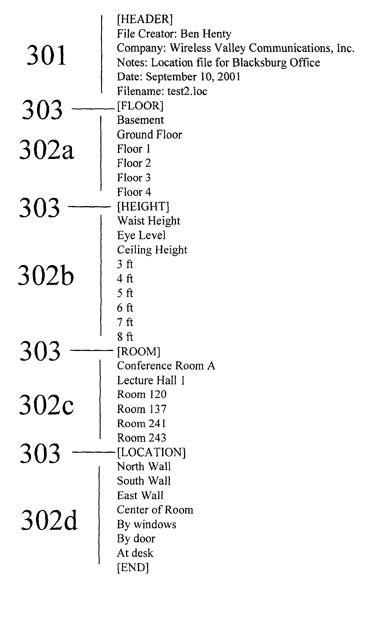
That is, in prior art products, a map is a simple
bitmap image that does not represent or point out to the user the physical locations of walls, ceilings, or floors that are found on campuses and in buildings, and the measurements from the prior art products and patents do not provide any location-specific text or icon that allows the user to easily determine through context, before, during, or after the
field survey, the general location or specific meaning of the measurement.
Furthermore, in the prior art described above, there is not the ability for a user to pre-assign or to assign during or after a measurement survey some specific visual demarcations, such as symbols, shapes, icon
graphics, or particular text strings, that may be displayed in real-time to the user of the product during the actual survey or in subsequent surveys.

