Method for aiming and adjusting microwave antenna during installation, and apparatus

a technology of directional microwave antenna and antenna, which is applied in the direction of transmission monitoring, instruments, wireless communication, etc., can solve the problems of difficult to carry any additional equipment to measure the signal strength, the communication between the antennas and the radio system behind the antenna, and the difficulty of finding well-trained professionals

Inactive Publication Date: 2002-07-11
ZHANG FRLIN ZHIGANG
View PDF6 Cites 20 Cited by
  • Summary
  • Abstract
  • Description
  • Claims
  • Application Information

AI Technical Summary

Problems solved by technology

Any visible object or non-visible interference in the electromagnetic wave path may cause problem to the communication between both ends of the antennas as well as the radio systems behind the antennas.
But, when the installer is high up at the roof of a tall building or at the high place of a high tower, it is very hard to carry any additional equipment to measure the signal strength so as to aim the antenna.
Nonetheless, well skilled professional is very hard to find.
Obviously, it is very easy for a microwave communication system being interfered by other unknown resource.
This means, even though a microwave communication system has enough signal strength detected, unknown interference can still cause problem to the communication of the system.
Thus, the prior art of setting up the system by aiming the antenna at the direction, at which the system or the test equipments detect the strongest signal strength is not a secure method to guarantee the best signal to noise ratio for the system.

Method used


Image

  • Method for aiming and adjusting microwave antenna during installation, and apparatus
  • Method for aiming and adjusting microwave antenna during installation, and apparatus
  • Method for aiming and adjusting microwave antenna during installation, and apparatus

Examples


Embodiment Construction

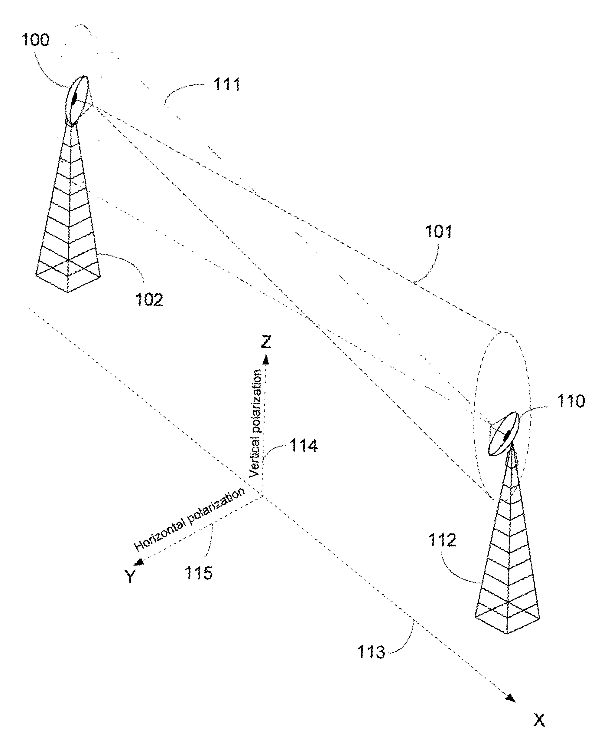
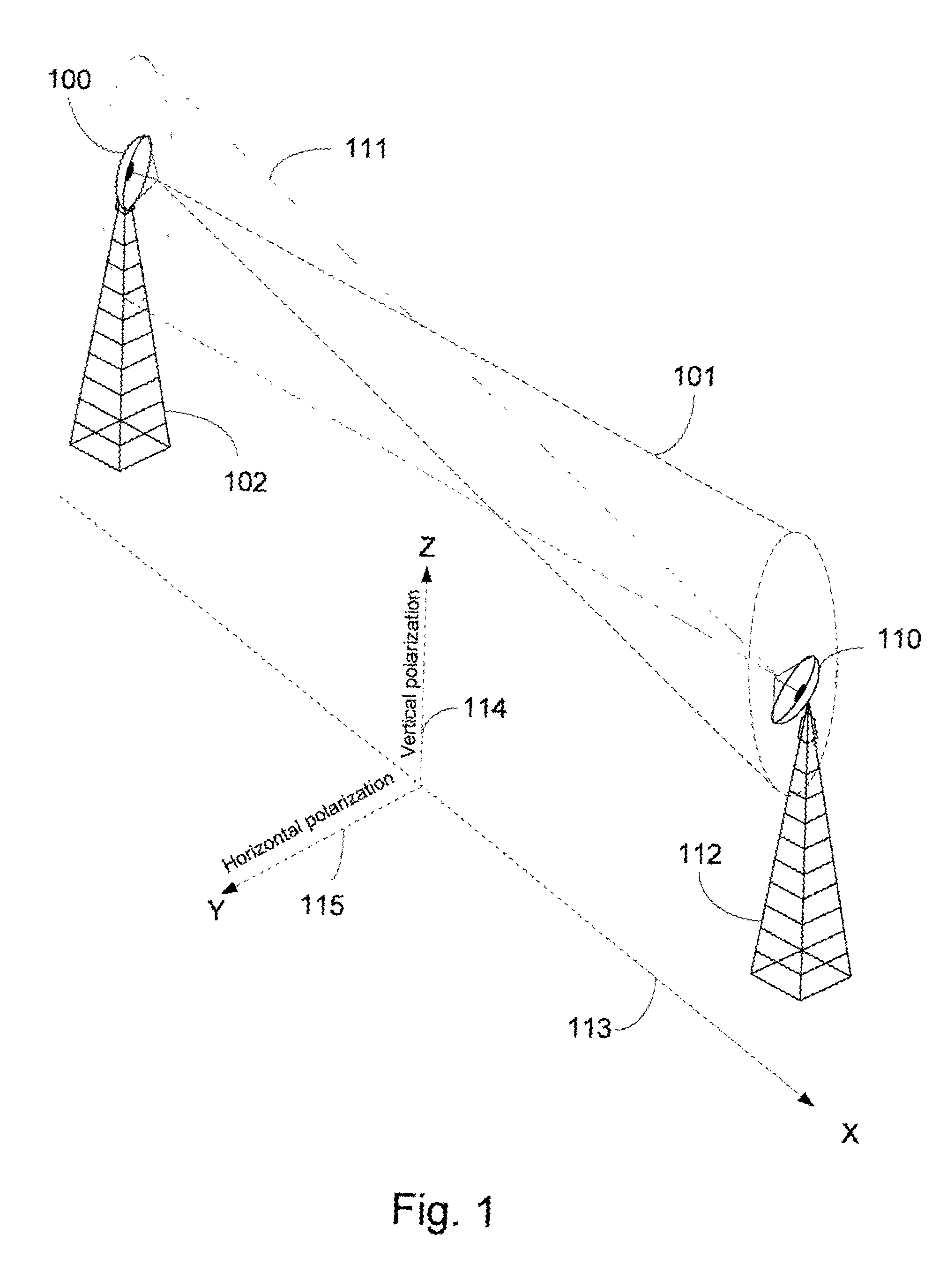
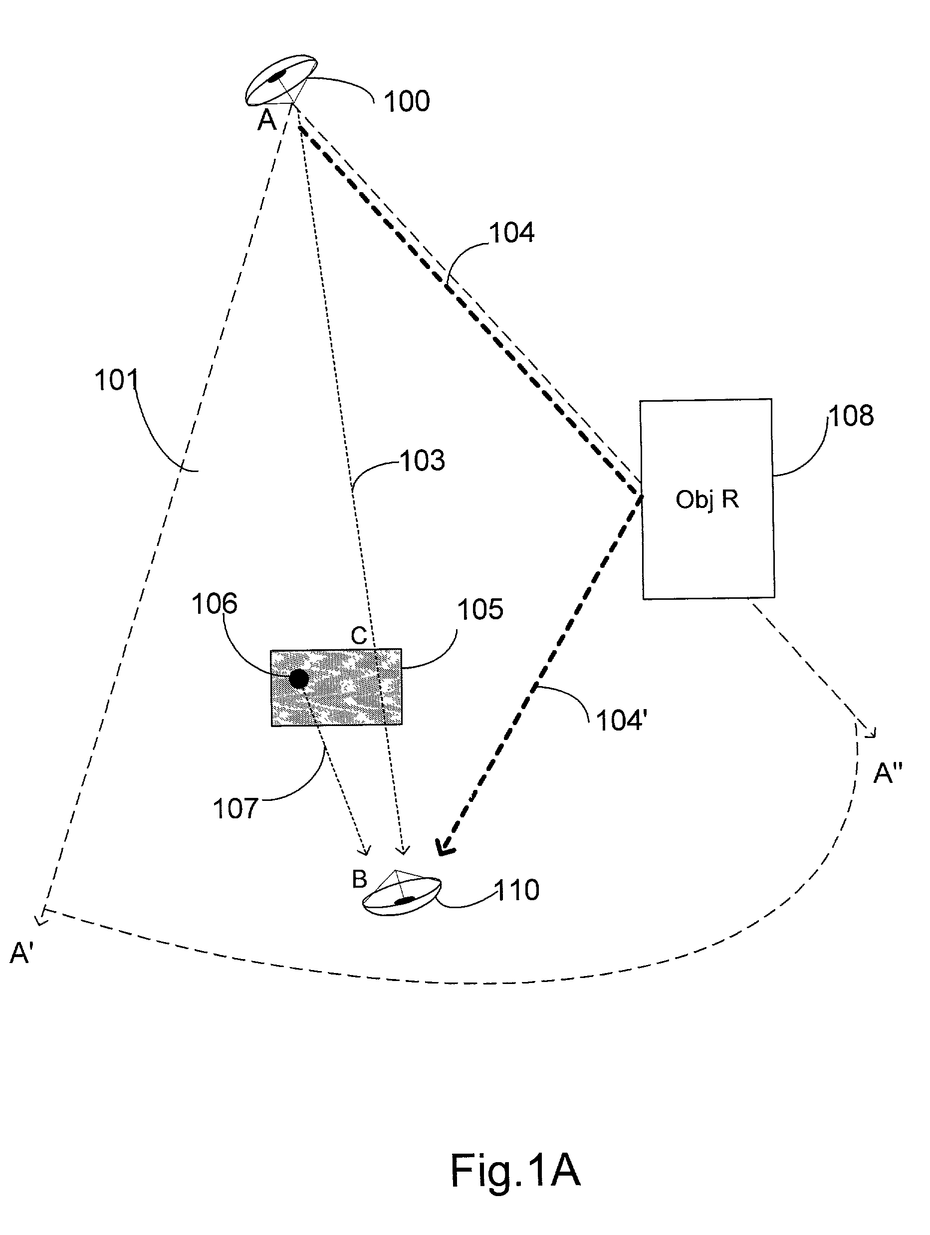
[0029] It is a common knowledge in the microwave communication industry that the microwave communication requires the antennas to send as well as receive signals from other antennas. The method according to the present invention not only assists in installing the second antenna, but can also be used in adjusting the pre-installed first antenna, if necessary, to be able to be placed in a best link quality position in relationship to the second antenna.

[0030] In the present invention, the distance between the first microwave antenna and the second microwave antenna is limited to capabilities of receive sensitivity of the radio systems that the microwave antennas are connected to. The present invention can be used in any wireless telecommunications where the signals are transmitted from one source and are received at another place where the receiving antenna needs to be adjusted for a best link quality. Examples of these wireless telecommunications are LMDS wireless local loop, MMDS sy...


PUM


Abstract

The present invention disclosures a method for aiming antennas during the installation of microwave communication systems. By computerized link quality monitoring mechanism, the software of the computer system can monitor the link quality of the link during the aiming of the installation. The link quality comprises the performance of data communication status, and the signal strength and noise tests result. By aiming and installing the antenna at the best link quality direction, the microwave communication system will work at best performance status. The software system also will guide the installer to follow certain procedures and finally affix and aim the antenna to the best direction. There are no extra equipments, such as high cost spectrum analyzer needed. And also, no super high-skilled microwave experts are needed to install and setup the microwave communication system.

Description

[0001] This application claims the benefit of the Provisional Patent Application Ser. No. 60 / 260,297 filed Jan. 1, 2001.BACKGROUND--FIELD OF INVENTION[0002] This invention is concerned with a method for aiming a directional microwave antenna during the installation, specifically to a computer guided microwave antenna aiming method to get the best link performance for digital microwave communication system.BACKGROUND--DESCRIPTION OF PRIOR ART[0003] Microwave antennas are usually essential parts of microwave telecommunication systems. These microwave antennas are most likely placed on the top of high structures such as antenna towers or high buildings. Each antenna is placed in a certain distance from another antenna. Installing microwave antennas requires lining up two antennas in a certain way that the microwave transmission and receive will be in the best situation.[0004] The quality of microwave signal transmission depends on many environmental characters. The earth surface terrai...

Claims


Application Information

Patent Timeline
Patent Type & Authority Applications(United States)
IPC IPC(8): H01Q1/12H04W24/02
CPCH01Q1/1257H04W24/02
Inventor ZHANG, FRANKLIN ZHIGANG
Owner ZHANG FRLIN ZHIGANG
Why Eureka
Try Eureka