
Method and apparatus for supporting parity protected raid in a clustered environment

a clustered environment and parity protection technology, applied in the field of data storage systems, can solve the problems of high cost ratio of fault tolerant storage, difficult implementation of software raid-3 controllers, and the inability of the raid-0 to increase reliability

Inactive Publication Date: 2002-07-11
IBM CORP
View PDF17 Cites 69 Cited by
  • Summary
  • Abstract
  • Description
  • Claims
  • Application Information

AI Technical Summary

Problems solved by technology

RAID-0 does not increase reliability, since it does not provide for additional redundancy.
Additionally, the cost ratio of fault tolerant storage is high.
Software RAID-3 controllers are difficult to implement, and hardware RAID-3 controllers are generally of medium complexity.
RAID-4 provides a high read data transaction rate, but can require a complex controller design.
RAID-4 arrays generally have a low write transaction rate and it can be difficult to rebuild data in the event of a disk failure.
Disk failures can compromise throughput, however, and RAID-5 controllers can be difficult to implement.
RAID-6 has the highest reliability, but is not widely used due to the difficulty in implementation and double parity computations.
When shared parity protected RAID data (e.g., RAID-4 data, RAID-5 data, RAID-6 data, and their variations) is supported by multiple nodes (either with RAID adapters or software RAID) in a cluster, the RAID parity update may be incorrect when two or more nodes change different data items in the same RAID stripe at about the same time.
In other words, when there is more than one master managing the storage array in a RAID, there can be problems.
Data integrity may be lost if updates to panty are not synchronized properly.
Consequently, such a solution does not scale well with a larger number of nodes, and cannot handle the addition or deletion of nodes gracefully.
However, in small computer system interface (SCSI) systems (a system commonly utilized in RAID systems), such inter-adapter communication does not exist in a non-proprietary way.

Method used


Image

  • Method and apparatus for supporting parity protected raid in a clustered environment
  • Method and apparatus for supporting parity protected raid in a clustered environment
  • Method and apparatus for supporting parity protected raid in a clustered environment

Examples


Embodiment Construction

[0025] In the following description, reference is made to the accompanying drawings which form a part hereof, and which is shown, by way of illustration, several embodiments of the present invention. It is understood that other embodiments may be utilized and structural changes may be made without departing from the scope of the present invention.

Hardware Environment

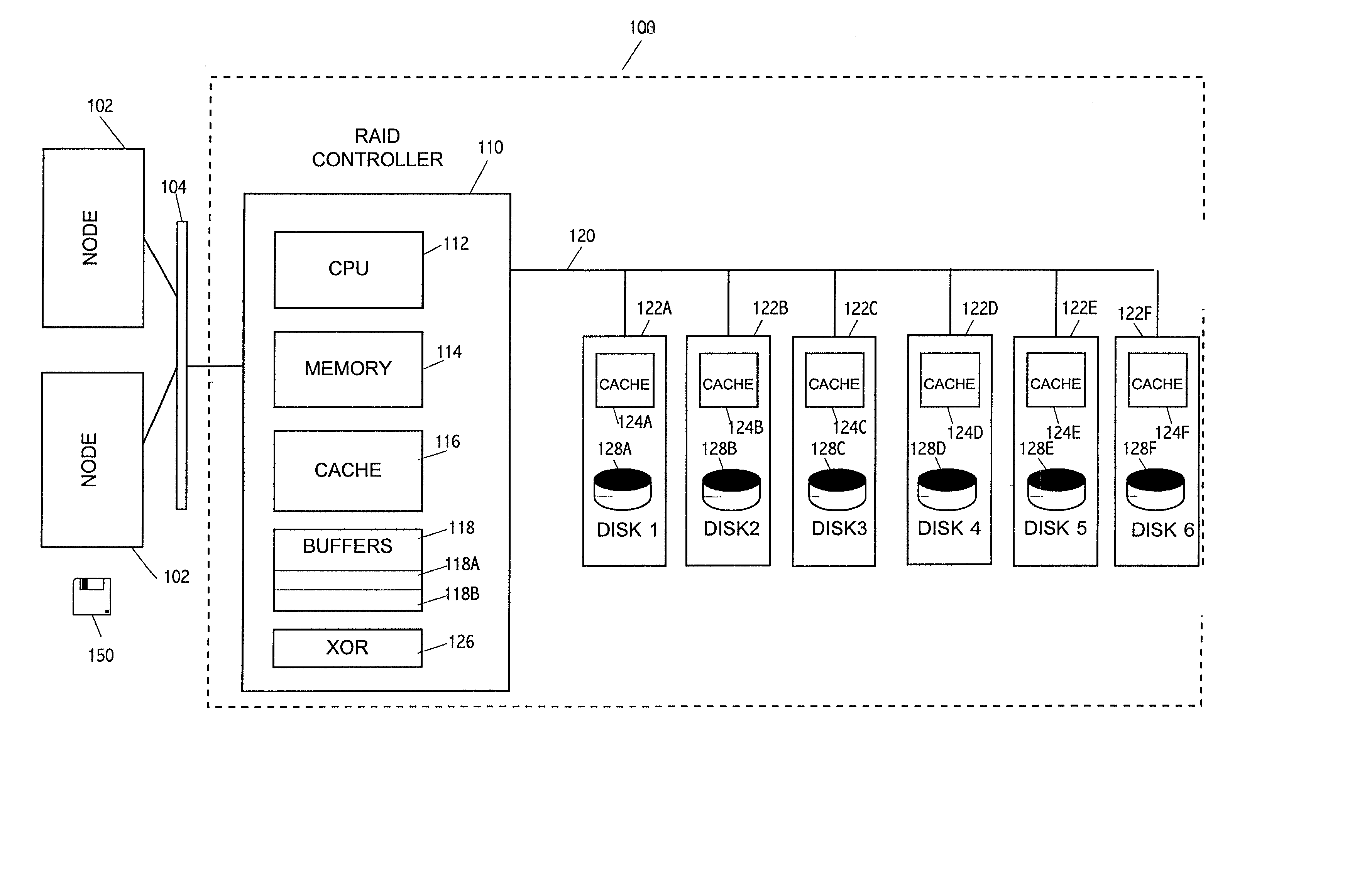
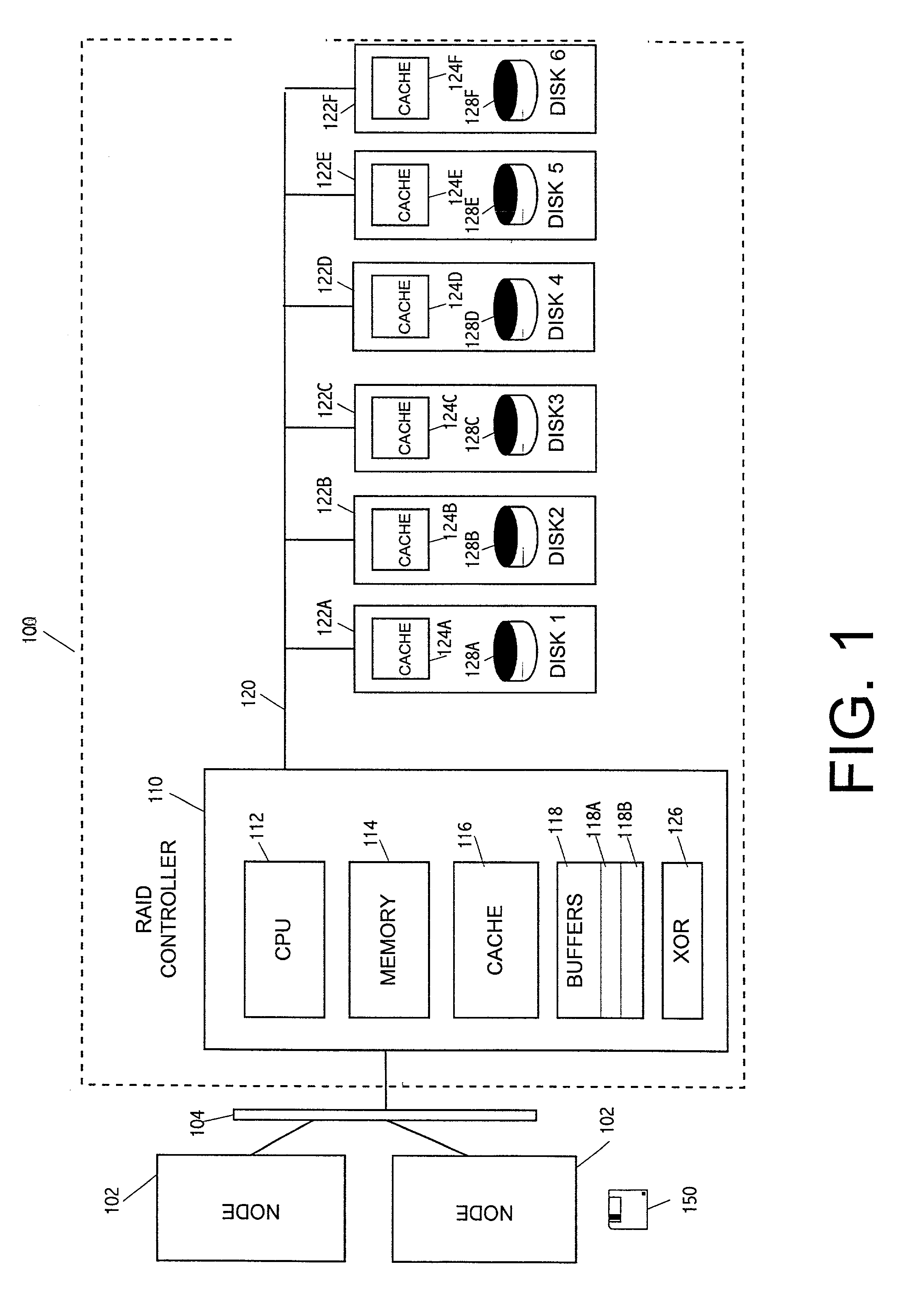
[0026] FIG. 1 is a block diagram showing a hardware environment implementing one embodiment of the present invention. A RAID array 100 accepts commands from one or more nodes 100-102 (such as a host computer, another RAID array, or a disk 128 in a RAID array) via an interconnecting bus 104. These commands comprise, interalia, commands to write data to the RAID array 100 and commands to read data from the RAID array 100. Ordinarily, the smallest unit of data that can be written to and read from the RAID array 100 is one user sector, typically 512 bytes. One or more nodes 100-102 could be interconnected with the RAID array...


PUM


Abstract

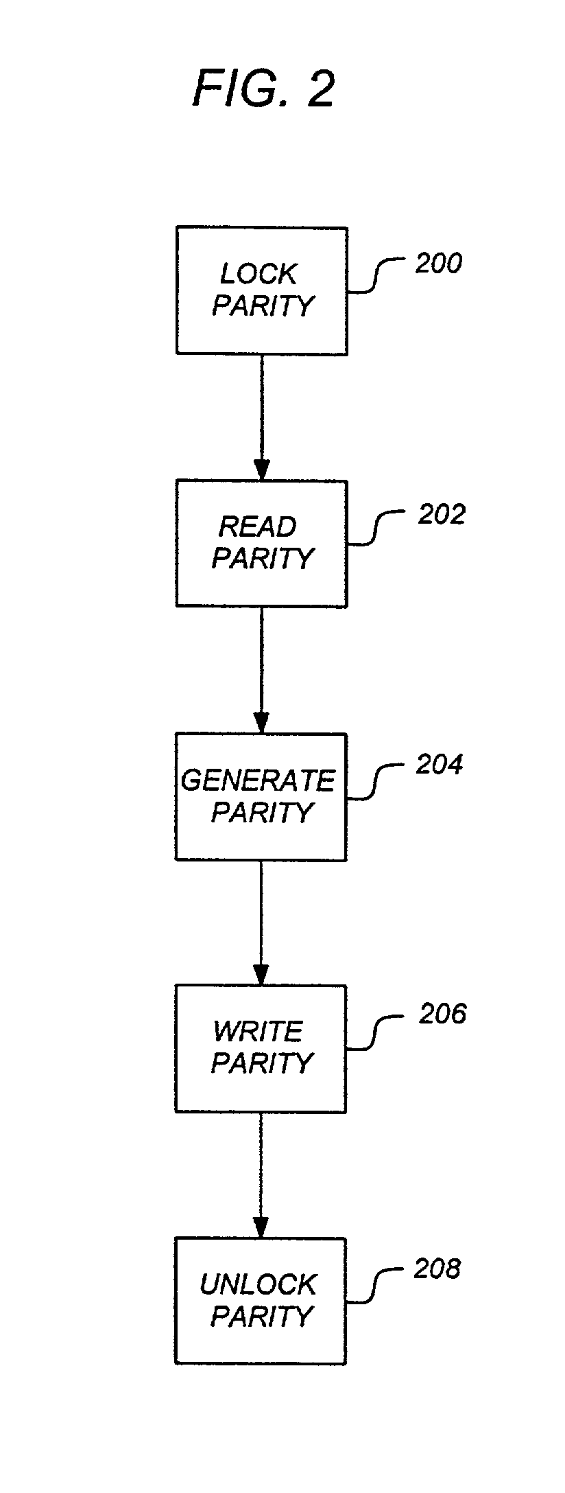
To address the requirements described above, the present invention discloses a method, apparatus, article of manufacture, and a locking structure for supporting parity protected RAID in a clustered environment. When updating parity, the parity is locked so that other nodes cannot access or modify the parity. Accordingly, the parity is locked, read, generated, written, and unlocked by a node. An enhanced protocol may combine the lock and read functions and the write and unlock functions. Further, the SCSI RESERVE and RELEASE commands may be utilized to lock / unlock the parity data. By locking the parity in this manner, overhead is minimized and does not increase as the number of nodes increases.

Description

[0001] This application is related to the following co-pending and commonly assigned patent application, which application is incorporated by reference herein:[0002] U.S. patent application Ser. No. 09 / 203,101, entitled "Method for Managing Concurrent Processes Using Dual Locking", by Richard Francis Freitas, et. al., Attorney Docket No. AM9-98-046, filed on Nov. 30, 1998.[0003] 1. Field of the Invention[0004] The present invention relates to data storage systems, and in particular, to a method and apparatus for supporting parity protected RAID in a clustered environment.[0005] 2. Description of the Related Art[0006] The ability to manage massive amounts of information in large scale databases has become of increasing importance in recent years. As businesses begin to rely more heavily on large scale database management systems, the consequences of hardware-related data losses intensify, and the security, reliability, and availability of those systems becomes paramount.[0007] One wa...

Claims


Application Information

Patent Timeline
IPC IPC(8): G06F9/00G06F12/00G06F13/00H03M13/00
CPCG06F11/1076G06F2211/1028H03M13/19
Inventor CHIU, LAWRENCE YIUM-CHEEHSU, WINDSOR WEE SUNYOUNG, HONESTY CHENG
Owner IBM CORP
Learn More