
Visual architecture software language

a software language and software technology, applied in the field of visual architecture software language, can solve the problems of destroying the inherent architecture of the system, and difficult to understand and change software systems

Inactive Publication Date: 2002-07-18
CALYTRIX TECH
View PDF7 Cites 53 Cited by
  • Summary
  • Abstract
  • Description
  • Claims
  • Application Information

AI Technical Summary

Benefits of technology

0029] The invention may further include conversion means for converting conventional software applications to components, said conversion means providing system level translation between the inputs and outputs of the conventional software application and the required visual architecture software language inputs and outputs.
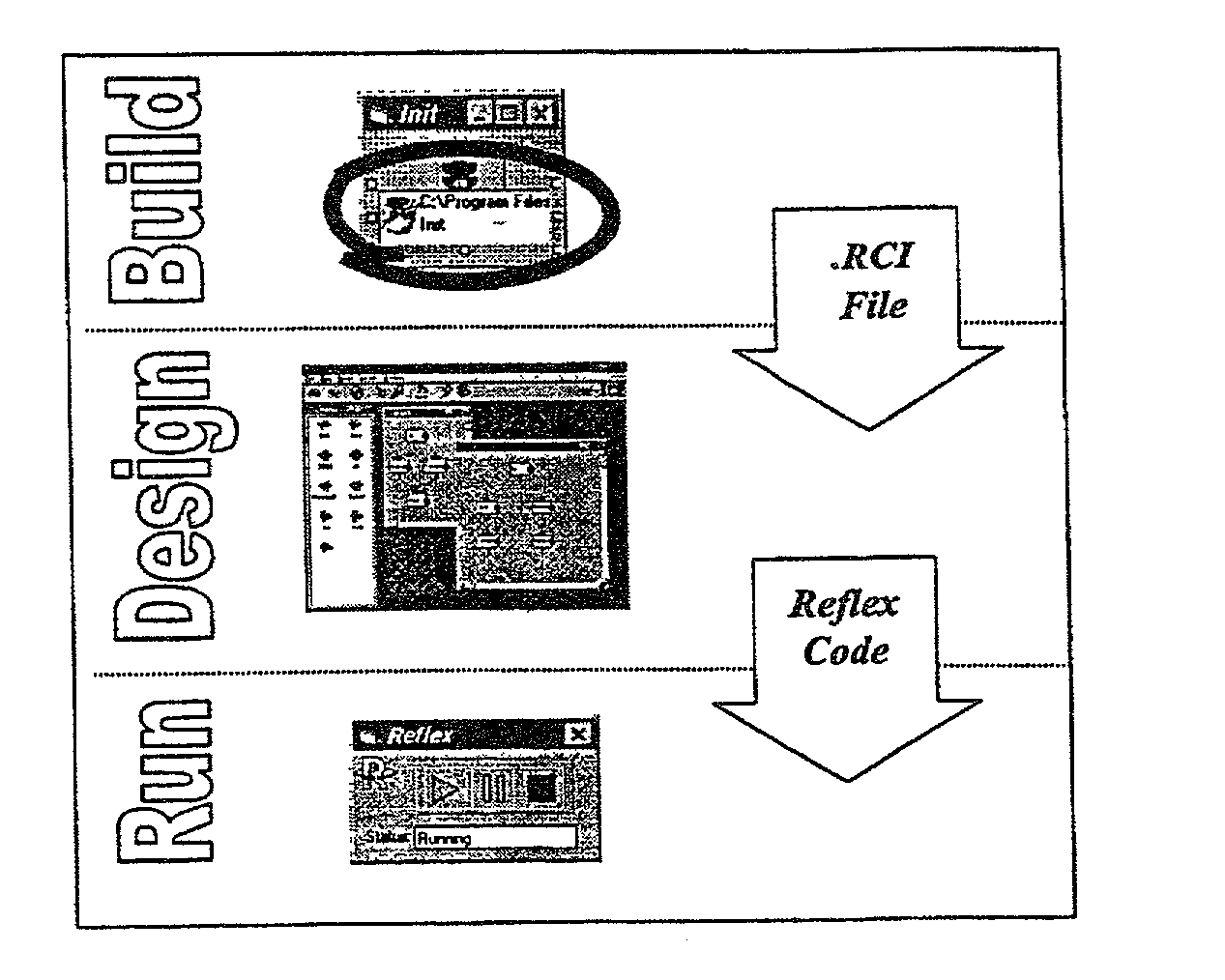
0030] In preference, the compiling means maintains a distinct separation between data integration requirements and sequence control on one hand and the computational or functional specification on the other hand. The separation of functions is maintained throughout all stages of the development and delivery process, including but not limited to design, development, implementation and project management.

Problems solved by technology

In other words the distorting sequential arrangement of code effectively destroys the inherent architecture of a system.
Such software systems are very difficult to understand and change, they lack appropriate spatial organisation and visual clues that could indicate how components are related and interact.
This lack of spatial separation among components sharply increases the complexity of software and makes it hard to understand.
To make matters worse, the lack of separation of components and data greatly increases the chances of unintended side-effects and hence problems of reliability, security and failure.
The AT&T system allows reuse of software components, but it does not address the fundamental difficulty in design and programming of complex software systems.
It is impossible to visualise the function of the software.
The software systems of the last forty years, including the AT&T system, have created a complexity barrier that prevents people from effectively exploiting their visual and spatial abilities (which are very highly developed in humans) in the design, representation and maintenance of computer-based systems.
A major problem with RMI is the level at which components must be addressed and used.
The line or separation between components and code also tends to blur, as programmers build structures to support the component, hence affecting reusability.
Furthermore, they do not support visual development or represent the initial high-level design.

Method used


Image

  • Visual architecture software language
  • Visual architecture software language
  • Visual architecture software language

Examples


example 2

[0073] A natural extension of example 1 is the feed back loop shown in FIG. 9. Component A may use its own transformed data for further processing or for possibly recursive transformations. Although this may seem obvious it is not always a supported behavior in many integration models.

example 3

[0074] FIG. 10 displays the effect of memory buffering on the data flow. Components B and C may be sharing data directly or the data may be stored in a memory buffer. The buffer can be set up to hold a single item that is overwritten as new data becomes available. Alternatively, the buffer may be a shared buffer that holds a collection of items for use by all downstream components. Finally, the buffer may be unique and independent for each downstream component. The type of buffering employed affects the behavior of the process.

example 4

[0075] Two components may send data to a single downstream component, C, as shown in FIG. 11. Two possibilities, an `OR` or an `AND` relationship, are shown. If an `OR` relationship is in use then input from either component A or B will trigger C. However, if an `AND` condition is in place then input must come from both upstream components. This characteristic is particularly useful when trying to synchronize data streams or when confirmation is needed that a data buffer is available.

[0076] In the scenario where a single downstream component receives two or more input channels, it is possible to turn data priority on for any or all of the data sources. Data priority will ensure that the currently active input channel's buffer is emptied or exhausted by the downstream component before it relinquishes control to an alternative input source. This allows uninterrupted processing of any given data source.


PUM


Abstract

A visual architecture software language is described comprising reusable components and programmable channels. The reusable components define discrete software modules in any language. The programmable channels define data flow and control flow between components. A visual representation of functional computer software is generated in a visual environment by integrating the components and channels. A compiling means converts the visual representation into executable code in the form of executable instructions and data tables. The visual architecture software language may also include an integration server that executes the executable code. A system incorporating the language and a method of programming with the language is also disclosed.

Description

[0001] The invention relates to a visual architecture software language (VASL) that facilitates component based design and implementation of complex software systems. In particular, the invention provides a hidden-code system for developing complex programs from components and channels.BACKGROUND TO THE INVENTION[0002] Large software systems are currently represented textually in code, large numbers of modules arranged sequentially one after the other, page after page or screen after screen. For example, the software that runs the Boeing 777 aircraft consists of 4 million lines of code--that's approximately 16 kilometers of line printer output. This linear structure gives few clues as to how the overall system is organised, how individual modules are related to one another or how information flows between modules. In other words the distorting sequential arrangement of code effectively destroys the inherent architecture of a system.[0003] Such software systems are very difficult to ...

Claims


Application Information

Patent Timeline
Patent Type & Authority Applications(United States)
IPC IPC(8): G06F8/34G06F9/44
CPCG06F8/34
Inventor PARR, SHAWNDROMEY, GEOFF
Owner CALYTRIX TECH
Learn More