
Right-angle coaxial connector

a technology of coaxial connector and right-angle, which is applied in the direction of coupling device connection, coupling protective earth/shielding arrangement, electric discharge lamps, etc., can solve the problems of low productivity and the ground terminal serving as a metal shell, and achieve excellent connection state therebetween

Inactive Publication Date: 2002-07-25
MOLEX INC
View PDF0 Cites 4 Cited by
  • Summary
  • Abstract
  • Description
  • Claims
  • Application Information

AI Technical Summary

Benefits of technology

[0011] According to the present invention, the coaxial plug has one signal terminal and the plurality of ground terminals disposed around the signal terminal, and these terminals are each in the form of the pin type, and protrudes from the surface of the insulative plug main body. In particular, the ground terminal is not the cylindrical, but rather is a pin type in contrast to the prior art, and therefore clearances are formed between the terminals. Consequently, even if metal waste, particles, and the like find their way into the clearances between the terminals, they can easily pass through the clearances and they can be removed easily therefrom. Accordingly, the possibility of electric short circuits can be eliminated. Further, the entire housing is formed of resin, and a ground terminal serving also as a metal shell, which is low in productivity, is not used. Accordingly, the mass production applicability is improved, and manufacture with low cost can be realized.
[0012] It is preferable that the ground terminals of the invention are arranged such that distances between adjacent ground terminals are also equal to each other. By setting the clearances between adjacent terminals equal, the electric field distribution around the signal terminal can be made uniform, and the shielding effect by the ground terminals can be enhanced.
[0013] It is preferable that the ground terminals are arranged such that distances from the signal terminal to the ground terminals are also equal to one another. By setting the distances from the signal terminal to the ground terminals to be equal to one another, the electric field distribution around the signal terminal can be made more uniform, and the shielding effect by the ground terminals can be enhanced.
[0014] In another embodiment of the invention, a surface of the plug main body is partially formed into a planar surface extending in an axial direction of the cable and the signal terminal is disposed at a central portion of the planar surface protrudes from the planar surface, while the ground terminals are disposed around the signal terminal. By arranging the terminals on the planar surface extending in the axial direction of the cable to be protruded from the planar surface, the form of the right-angle coaxial plug can be maintained, while a simple arrangement that makes it difficult for the metal wastes to enter into or to stay in the clearances between the terminals can be realized.
[0018] By providing the coaxial receptacle with the plurality of guide holes independently and respectively corresponding to the signal and ground terminals, even if minute metal wastes and so on find their way into the guide holes, a short circuit between the signal terminal and the ground terminal will not occur. Since the surface of the insulative housing has a planar portion, it can be contacted with the planar surface of the coaxial plug, thereby preventing the formation of a clearance between the receptacle and the plug.
[0019] In another embodiment, can also be used in which the insulative housing of the coaxial receptacle has a side surface intersecting the surface thereof, and a stopper portion is provided in a boundary portion to the planar surface of the plug main body so as to be contacted with the side surface of the insulative housing, thereby restricting a displacement of the plug main body in a direction about an axis of the signal terminal when the coaxial plug is connected to the coaxial receptacle. This construction makes it possible to reliably position the coaxial plug with respect to the coaxial receptacle, and maintain the excellent connected state therebetween.

Problems solved by technology

Further, the entire housing is formed of resin, and a ground terminal serving also as a metal shell, which is low in productivity, is not used.

Method used


Image

  • Right-angle coaxial connector
  • Right-angle coaxial connector
  • Right-angle coaxial connector

Examples


first embodiment

[0032] Hereafter, the present invention will be described with reference to FIGS. 1 to 6.

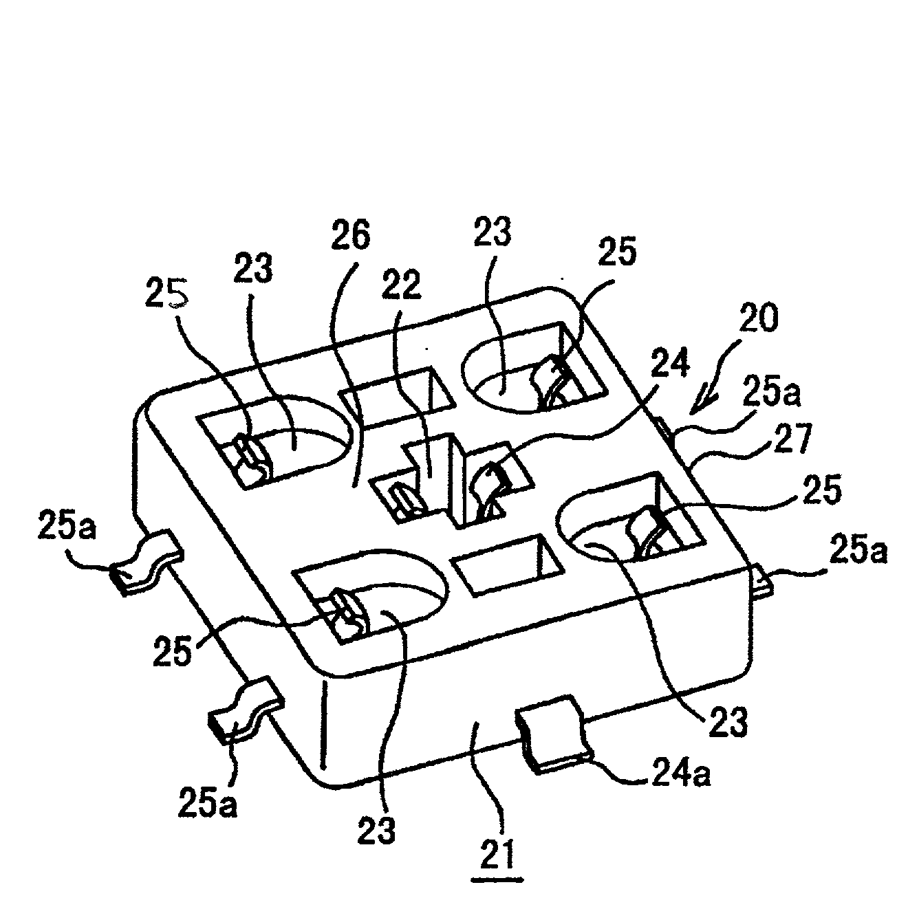
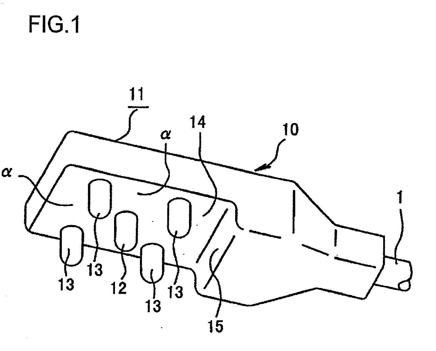
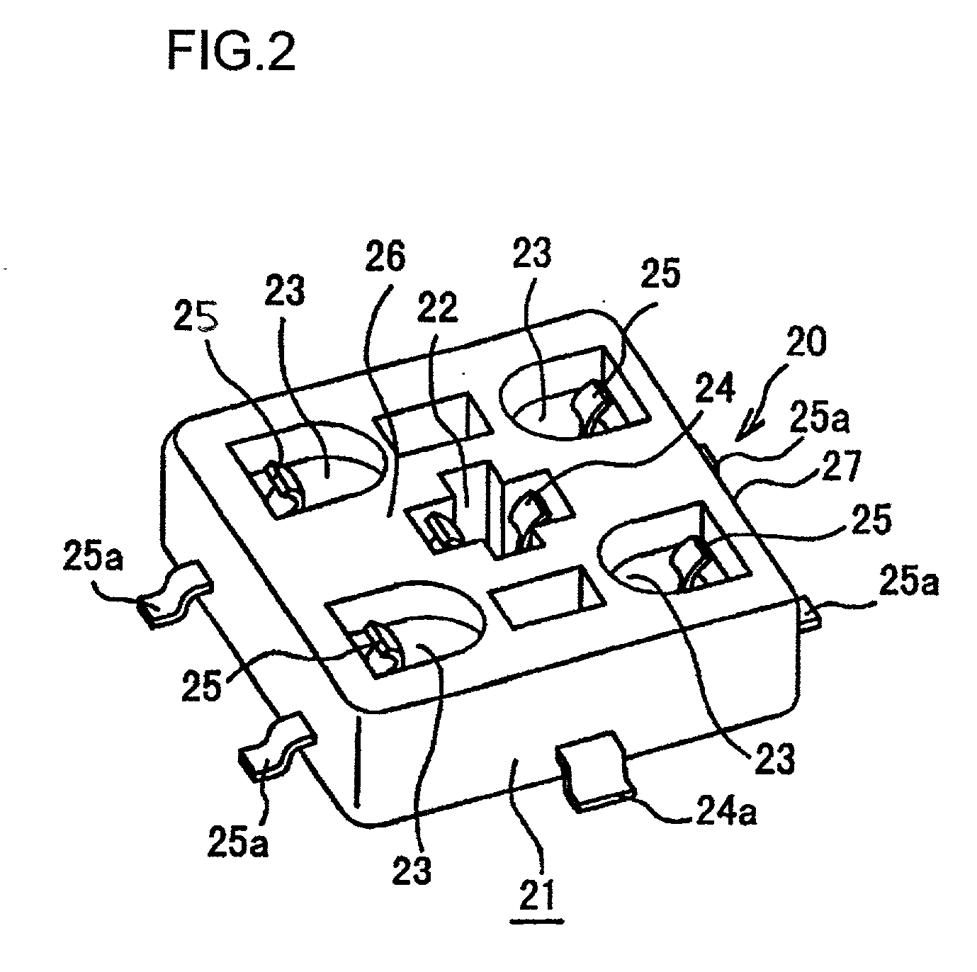
[0033] In the first embodiment, a miniature right-angle coaxial connector is shown. FIG. 1 is a perspective view of a coaxial plug, and FIG. 2 is a perspective view of a coaxial receptacle. The plug and receptacle are engageable together.

[0034] The right-angle connector shown in these drawings is provided with a coaxial plug 10 provided at an end of a cable 1, and a coaxial receptacle 20 electrically connected to the coaxial plug 10 by inserting the coaxial plug 10 thereto. As shown in FIGS. 1, 4 and 5, the coaxial plug 10 has a plug main body 11 made of an insulative resin, and a plurality of pin type terminals 12 and 13 protruded from a surface of the plug main body 11. The plug main body 11 serves also as a housing of the coaxial plug 10.

[0035] The tapered pin type terminals 12 and 13 are classified into one signal terminal 12 and a plurality of ground terminals 13 disposed around the signal ...


PUM


Abstract

A right-angle coaxial connector is provided, which can eliminate a possibility of the electric short circuit, which is excellent in mass production applicability, and which can be manufactured with low cost. The right-angle coaxial connector includes a coaxial plug 10 provided at an end of a cable 1, and a coaxial receptacle 20 electrically connected to the coaxial plug by inserting the coaxial plug therein. The coaxial plug 10 includes a plug main body 11 made of an insulative resin, and a plurality of pin type terminals protruded from a surface of the plug main body. The pin type terminals are divided into one signal terminal 12 and a plurality of ground terminals 13 disposed around the signal terminal. The ground terminals 13 are preferably arranged such that distances between adjacent ground terminals are set to be equal to one another.

Description

BACKGROUND OF THE INVENTION[0001] The present invention relates to a technology of a right-angle coaxial connector in which a pin-type terminal on a coaxial plug provided at an end of a cable is oriented in a direction different by 90 degrees from an axial direction of the cable.[0002] The right-angle coaxial connector includes a coaxial plug and a coaxial receptacle. The coaxial plug is used, for example, such that the coaxial plug is provided at an end of a coaxial cable. The coaxial receptacle is used, for example, such that the coaxial receptacle is mounted to a board or the like.[0003] In association with recent tendency toward small-size and light-weight electronic equipments, rapid progress has been made in miniaturizing coaxial connectors per se. Japanese Utility Model Application Laid-open No. Hei 5-33481 discloses particularly a technology of a right-angle coaxial connector, in which the thickness of a coaxial plug can be reduced particularly. Japanese Patent Application L...

Claims


Application Information

Patent Timeline
Patent Type & Authority Applications(United States)
IPC IPC(8): H01R103/00H01R13/648
CPCH01R24/50H01R2103/00
Inventor NODA, ATSUHITO
Owner MOLEX INC
Learn More