This helps you quickly interpret patents by identifying the three key elements:
Problems solved by technology
Method used
Benefits of technology
Benefits of technology
[0028] It is, accordingly, a first object of the present invention to route variable-length connectionless information, such as LAN information, through a connection-oriented ATM network in a form of fixed-length cells efficiently, at high speed, thereby realizing the connection between LANs.
[0029] It is a second object of the present invention to solve various problems encountered in achieving the first object, i.e., in realizing the connection between LANs through the ATM network. One of the problems is simultaneous transmission of the same information from a certain LAN to two or more other LANs. In this case, it is the second object to accommodate connectionless information in the ATM network and transfer the information not only to a single destination but also to two or more destinations designated by, for example, a group address at high speed, efficiently.
[0030] It is a third object of the present invention to perform the detection of cell errors in the ATM network and processes associated with the cell error detection efficiently, thereby reducing delays involved in detecting errors and to detect errors on the messages level in the cell stage, thereby eliminating the need for disassembly buffers for detecting message errors.
Problems solved by technology
One of the problems is simultaneous transmission of the same information from a certain LAN to two or more other LANs.
Method used
Image
Click on the blue label to locate the original text in one second.
Reading with bidirectional positioning of images and text.
Examples
second embodiment
[0249] Fig. 55 is a block diagram of the connectionless server inherent function section of the eighth invention.
[0250] In this figure, that blocks which are denoted by the same reference characters as in Fig. 54 described previously have the same functions, and thus their description is omitted here.
[0251] In Fig. 55, a quasi-EOM cell generating section 211 is provided.
[0252] In this figure, when a COM cell error is detected in the error detector 206a in the transmitting server 205a, MIDs are erased by the MID erase section 95, and a quasi-EOM cell is generated by the quasi-EOM cell generating section 211. The quasi-EOM cell is sent to the receiving server 205b over the transfer path 207.
[0253] In the receiving server 205b having the same arrangement as in Fig. 55, the quasi-EOM cell is separated by the segment type separator 90 and then sent to the MID erase section 95, so that it is erased. The quasi-EOM cell can be identified by setting its reserve bit to a specific value (for e...
first embodiment
[0254] According to this embodiment, as described above, the MID on the receive side can be released by the quasi-EOM cell generated by the sending server. Thus, this embodiments eliminates the need of the error alerting line 208 that is needed in the
third embodiment
[0255] Fig. 56 is a block diagram of the connectionless server inherent function section.
[0256] As shown, the third embodiment is equipped with a quasi-error cell generating section 212, which, when a COM cell error is detected in the error detector 206a of the transmitting server 205a, generates a quasi-error cell in the COM cell format and sends it on the transfer path 207.
[0257] It is preferable that the quasi-error cell, which is in the COM cell format and has erroneous data artificially entered into CRC bits, can easily be identified as being in error on the receive side.
[0258] Upon receipt of the quasi-error cell, the error detector 206b in the receive-side server 205b will detect the presence of an error. And the MID erase section 95 will erase and release the MID.
[0259] In this way, the third embodiment, when the error detector 205a in the transmitting server 205a detects an error in a COM cell, replaces it with a quasi-error cell for transmission to the receive side.
[0260] ...
PUM
Abstract
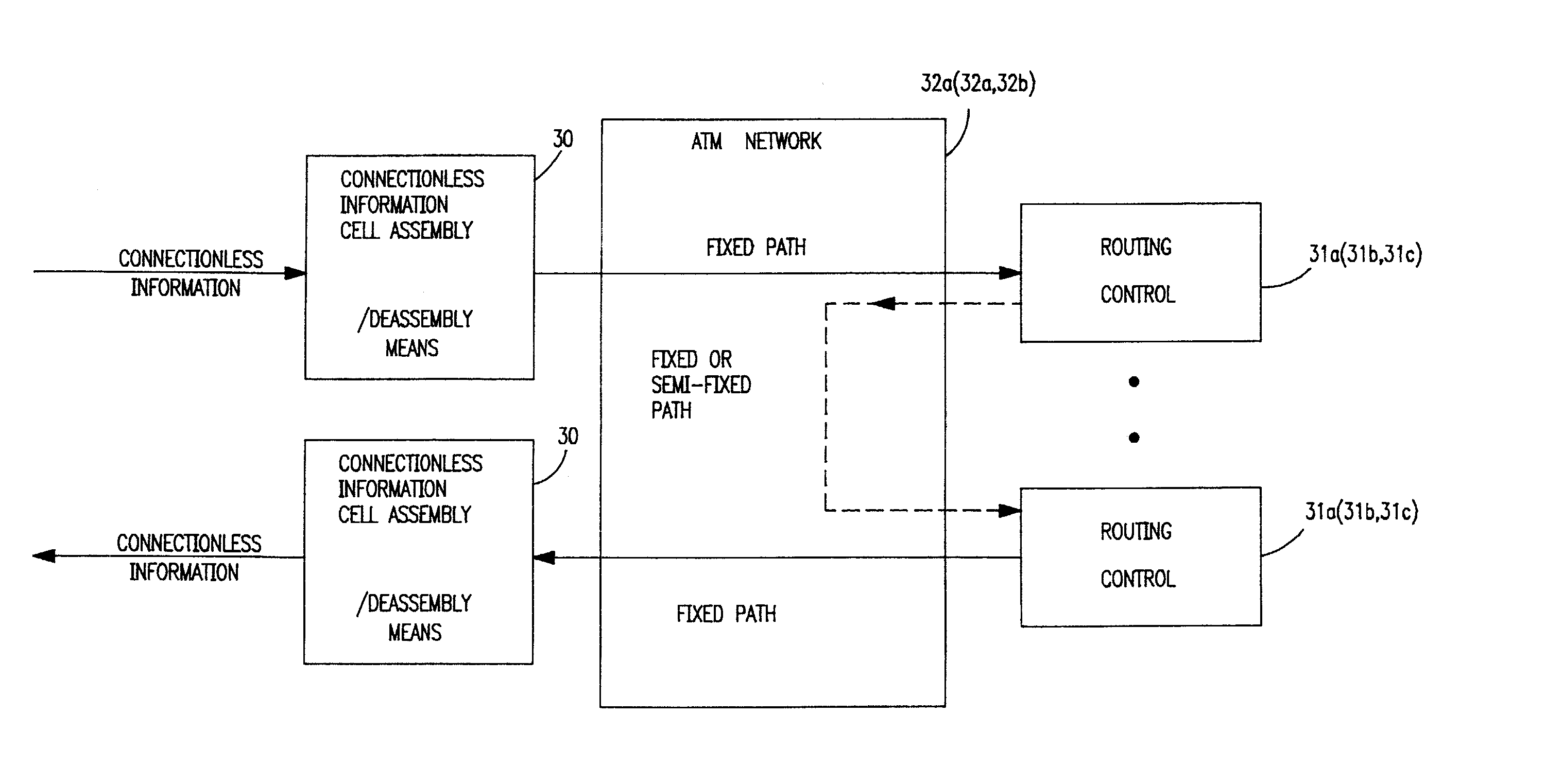
<heading lvl="0">Abstract of Disclosure< / heading> The object of the present invention is accommodating local connectionless information (data that is immediately transferred without establishing a path to a receive side), such as LAN data in a local area network, by an asynchronous transfer mode (ATM) network using a connection-oriented communication system (which makes data transfers after verifying that a path to the receive side has been established), thereby performing efficient, fast routing of connectionless information. A connectionless communicationsystem of the present invention is equipped with connectionless information cellassembly / disassembly means (30) for bi-directional conversion between variable-length connectionless information and fixed-length connectionless cells, routing control means (31) for analyzing a destination address of information in connectionless cells and controlling the routing of the connectionless cells; and an ATM network (32) for connecting the connectionless information cellassembly / disassembly means (30) and the routing control means (31) by a permanent virtual channel serving as a fixed path and connecting the routing control means together by a virtual channel serving as a semi-fixed path, whereby connectionless information is segmented into connectionless cells and the connectionless information is exchanged within the ATM network in connectionless cell units.
Description
Cross Reference to Related Applications[0001] This application is a continuation of application number 08 / 378,088 filed on January1995 and now abandoned, which is a continuation of parent application number 07 / 930,559, filed September 30, 1992, now abandoned.Background of Invention[0002] 1. Field of the Invention[0003] The present invention relates to an ATM-network-based connectionless communicationsystem which accommodates local connectionless information, such as data in a local area network (LAN), i.e., information sent by a system arranged to immediately transfer data with the address of a receiving terminal placed in the header of a message without establishing a path to the receiving terminal, in an asynchronous transfer mode (ATM) network that uses a connection-oriented communication system, i.e., a system which, before data transfer is made, verifies that a path to a receiving terminal has been established, and interconnects LANs.[0004] 2. Description of the Related Art[00...
Claims
Application Information
Patent Timeline
Application Date:The date an application was filed.
Publication Date:The date a patent or application was officially published.
First Publication Date:The earliest publication date of a patent with the same application number.
Issue Date:Publication date of the patent grant document.
PCT Entry Date:The Entry date of PCT National Phase.
Estimated Expiry Date:The statutory expiry date of a patent right according to the Patent Law, and it is the longest term of protection that the patent right can achieve without the termination of the patent right due to other reasons(Term extension factor has been taken into account ).
Invalid Date:Actual expiry date is based on effective date or publication date of legal transaction data of invalid patent.
Patent Type & AuthorityApplications(United States)

