
Contact-free display peripheral device for contact-free portable object

a portable object and peripheral device technology, applied in the field of peripheral objects, can solve the problems of user access to information, large size of the badge, and increased difficulty in displaying, so as to achieve the effect of reducing the drawbacks

Inactive Publication Date: 2002-08-08
ASK SA (FR)
View PDF14 Cites 23 Cited by
  • Summary
  • Abstract
  • Description
  • Claims
  • Application Information

AI Technical Summary

Benefits of technology

[0010] The purpose of the invention is to mitigate these drawbacks by supplying a contactless peripheral display for contactless portable objects, such as a smart card, having the capacity to display the information sent by the portable object reader or by the portable object itself, for a period of time long enough so that the user can consult it at all times, even when the portable object is not in the proximity of the reader, this display requiring only a small amount of energy to operate, or even no energy whatsoever.

Problems solved by technology

However, the drawback of having a display unit built into the reader is that the user can gain access to the information by passing the card in front of the reader.
While this is not a problem in the case of an identification card, it becomes much more problematic in the case of an electric wallet or transport card.
The latter is used particularly for electronic wallet cards and allows the balance remaining on the card to be consulted at all times. The major drawback of these badges is their size.
As such, contrary to a smart card, they cannot be carried in a wallet and must be carried in a pocket or purse.
Another drawback is that they require an internal power source.

Method used


Image

  • Contact-free display peripheral device for contact-free portable object
  • Contact-free display peripheral device for contact-free portable object
  • Contact-free display peripheral device for contact-free portable object

Examples


Embodiment Construction

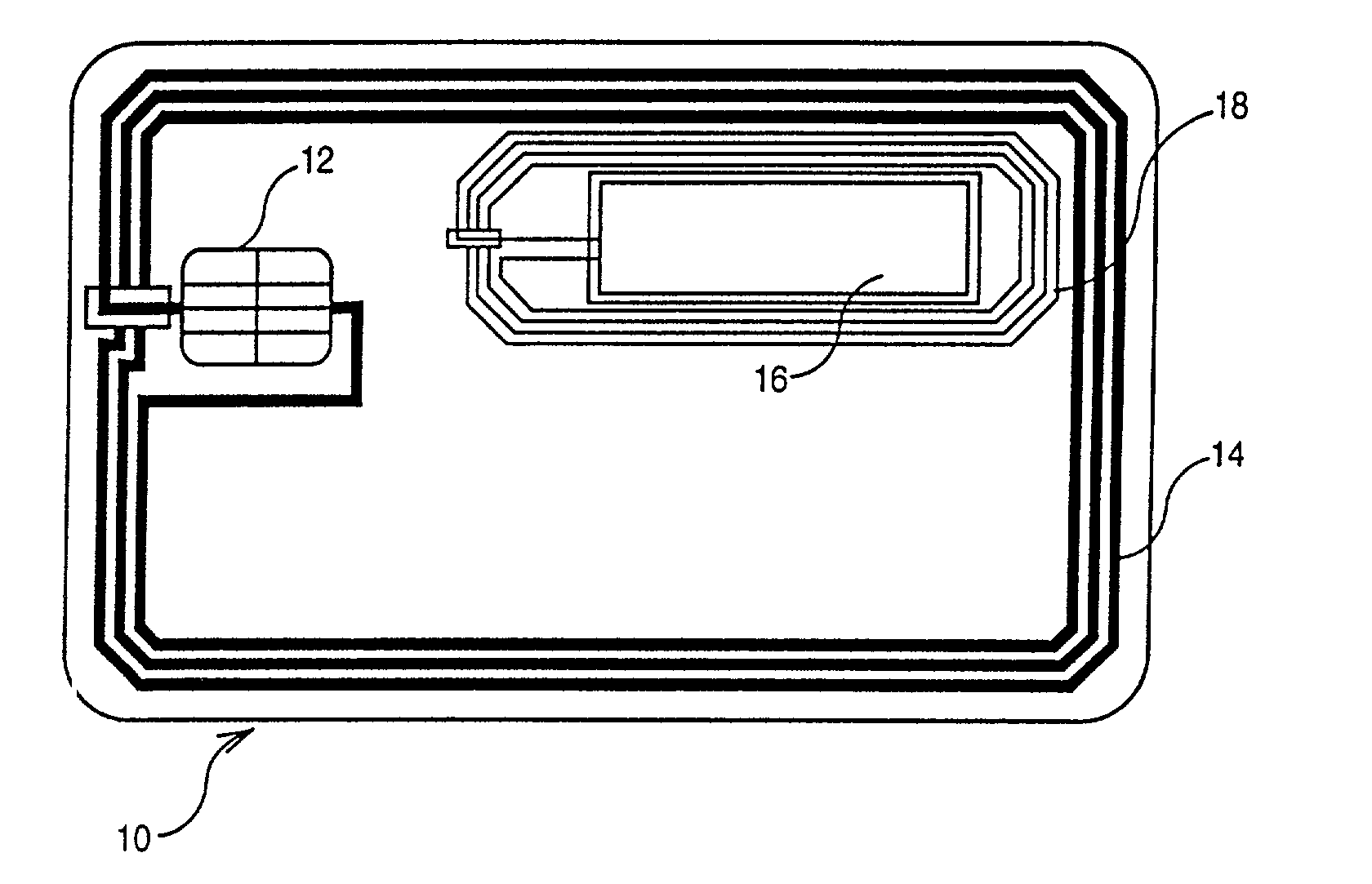
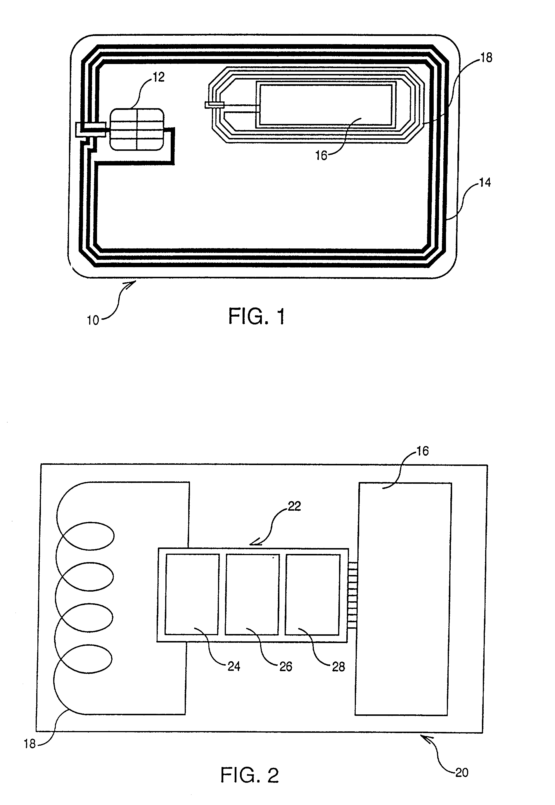
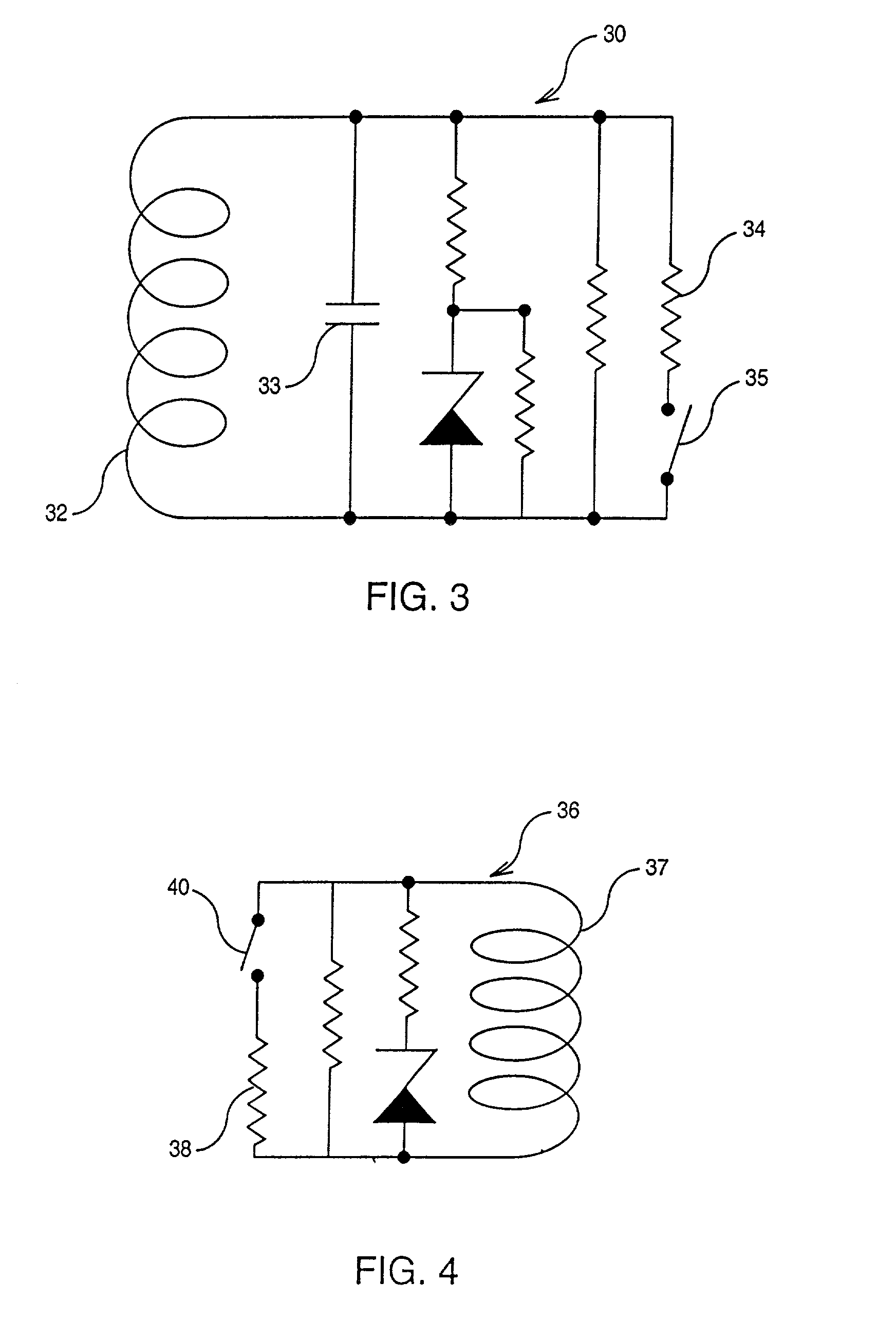
[0018] The peripheral display device according to the invention may thus be installed on a contactless portable object such as a smart card. FIG. 1 represents an ISO format contactless smart card featuring a built-in peripheral display device. This card 10 consists of a chip 12. When the card is placed in the field of the reader, this chip enters into communication with the reader by means of the card's antenna 14. This antenna consists of turns of increasing circumference. Each of the ends of this antenna is connected to the chip 12. The peripheral display device 20 consists of a chip (not visible in the figure), a screen 16 and a flat coil 18 connected to the chip of the peripheral display device and formed by turns of increasing circumference. The size of this flat coil varies depending on the special characteristics of the card with which the peripheral display device operates. The peripheral display device operates only when magnetically coupled to the card, at the working freq...


PUM

PropertyMeasurementUnit
coupling frequencyaaaaaaaaaa
carrier frequencyaaaaaaaaaa
frequencyaaaaaaaaaa

Abstract

The present invention concerns a peripheral display device for a portable contactless object such as a smart card (10) enabling information associated with the use of this portable object to be displayed. This peripheral device includes at least one chip, a display means (16) and a means for receiving energy and information (18), not connected by an ohmic contact to the portable object. This receiving means is a flat coil which plays the role of the secondary of a transformer, the primary of which is formed by the antenna (14) of the portable object, when the latter receives energy and information from a portable object reader via electromagnetic coupling.

Description

TECHNICAL FIELD[0001] The present invention concerns peripheral objects for portable contactless objects such as smart cards, and particularly a contactless peripheral display device.BACKGROUND ART[0002] Portable objects, such as smart cards, contact or contactless type, are currently widely used in numerous applications. It generally entails ISO format cards which are coupled to readers, by which they are remotely supplied, that is, by which they receive energy in the form of a magnetic field and with which they communicate. In the transport sector, such systems, called remote toll cards, have been developed by all of motorway operators in order to provide users with subscription possibilities and to simplify toll booth payment operations. Users of such systems present the cards in front of readers which are installed in the toll booths. Communication thus occurs between the card and the reader. This communication enables user recognition and the corresponding sum to be deducted fr...

Claims


Application Information

Patent Timeline
Patent Type & Authority Applications(United States)
IPC IPC(8): B42D25/305G02F1/13G06K19/07G06K19/077
CPCG06K7/10178G06Q20/201G06K19/07749G06K19/07703G06K19/077
Inventor PARRAULT, OLIVIER
Owner ASK SA (FR)
Learn More