Optical disc drive

Inactive Publication Date: 2002-08-08
PANASONIC CORP
View PDF1 Cites 32 Cited by
  • Summary
  • Abstract
  • Description
  • Claims
  • Application Information

AI Technical Summary

Problems solved by technology

For example, when the loop gain adjustment is performed in the recorded area and the optical pickup operates in the prerecorded area, or when the loop gain adjustment is performed in the

Method used


Image

  • Optical disc drive
  • Optical disc drive
  • Optical disc drive

Examples


embodiment 1

[0067] Hereinafter, a first embodiment of an optical disk apparatus according to the present invention will be described with reference to figures.

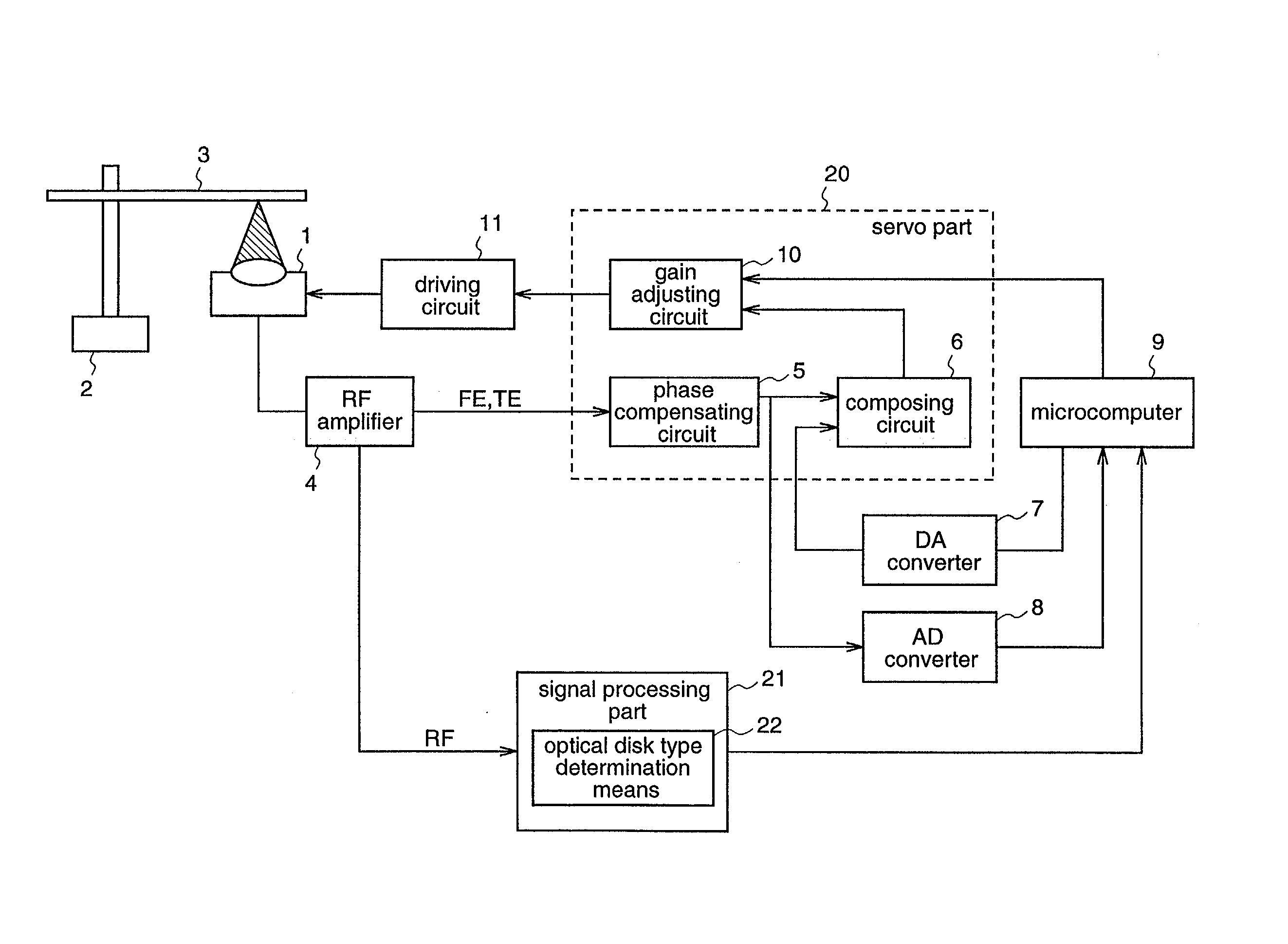
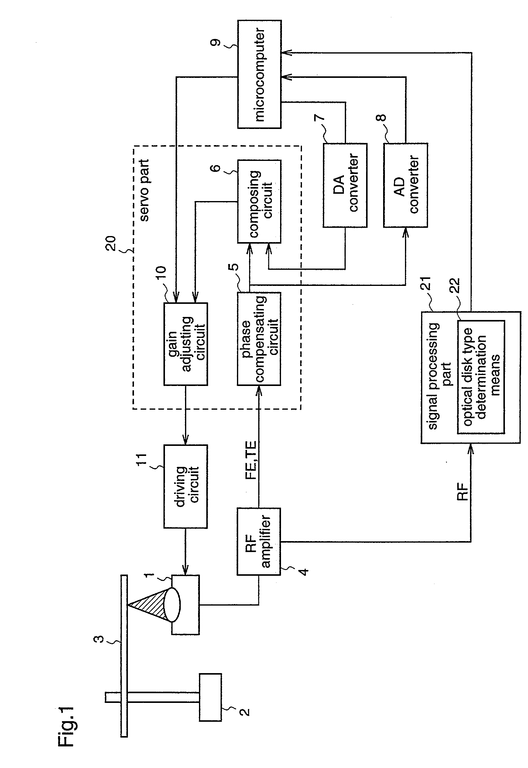
[0068] FIG. 1 is a block diagram illustrating a structure of the optical disk apparatus according to the invention, and the same reference numerals as those of the conventional optical disk apparatus shown in FIG. 22 denote the same parts.

[0069] In FIG. 1, numeral 1 denotes an optical pickup, numeral 2 denotes a spindle motor, numeral 3 denotes an optical disk, numeral 4 denotes an RF amplifier, numeral 5 denotes a phase compensating circuit, numeral 6 denotes a composing circuit, numeral 7 denotes a D / A converter, numeral 8 denotes an A / D converter, numeral 9 denotes a microcomputer, numeral 10 denotes a gain adjusting circuit, numeral 11 denotes a driving circuit, numeral 20 denotes a servo part, and numeral 21 denotes a signal processing part having an optical disk type determination means 22.

[0070] The optical pickup 1 comprises a las...

embodiment 2

[0098] Next, an optical disk apparatus which is provided with an adjustment value storage means for storing a gain adjustment value in the optical disk apparatus according to the first embodiment will be described as a second embodiment with reference to figures.

[0099] FIG. 5 is a block diagram illustrating the optical disk apparatus according the present invention. In FIG. 5, numeral 1 denotes an optical pickup, numeral 2 denotes a spindle motor, numeral 3 denotes an optical disk, numeral 4 denotes an RF amplifier, numeral 7 denotes a D / A converter, numeral 8 denotes an A / D converter, numeral 9 denotes a microcomputer, numeral 11 denotes a driving circuit, numeral 20 denotes a servo part, numeral 21 denotes a signal processing part having an optical disk type determination means 22 and a recorded / prerecorded determination means 23, numeral 24 denotes an adjustment value storage means having a first adjustment value storage means 24a and a second adjustment value storage means 24b, ...

embodiment 3

[0118] Next, an optical disk apparatus which is constructed so as to perform the loop gain adjustment by employing a PMA (Program Memory Area), in the optical disk apparatus according to the second embodiment will be described as a third embodiment with reference to figures.

[0119] A block diagram illustrating a structure of the optical disk apparatus according to this embodiment is the same as that in FIG. 5 which is employed for the description of the optical disk apparatus according to the second embodiment, and thus its description will be omitted here.

[0120] The loop gain adjustment operation of the optical disk apparatus according to the third embodiment will be described with reference to flowcharts in FIGS. 10 and 11.

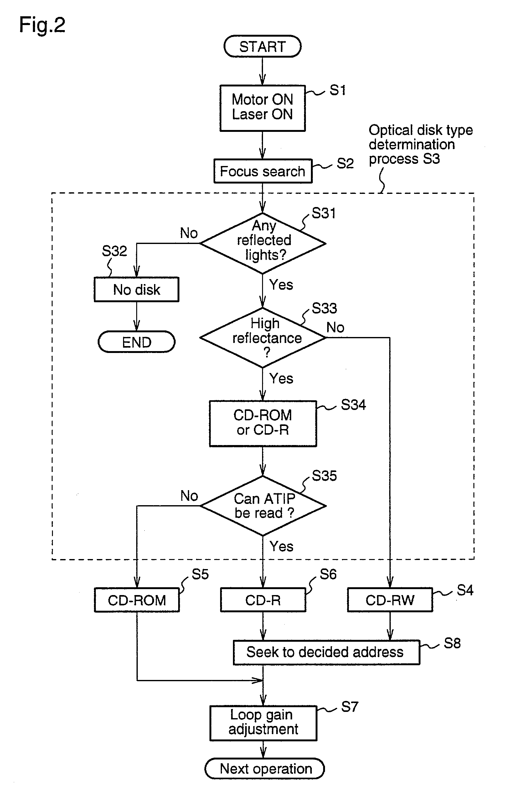
[0121] First, when the apparatus is started or an optical disk is inserted (mounted), the spindle motor is turned ON and the laser is turned ON (Step S1), thereby starting a spinup operation.

[0122] Next, a focus search operation is performed (Step S2) and determi...


PUM


Abstract

The present invention relates to loop gain adjustment of a focus/tracking servo in an optical disk apparatus, and provides an optical disk apparatus which can make the loop gain adjustment converge normally even in an optical disk in which prerecorded areas and recorded areas are mixed, and further which always has a stable servo system even when a gain is significantly varied due to changes in the disk state. When an inserted optical disk is determined to be a recordable optical disk by an optical disk type determination means 22, an optical pickup 1 is made seek a previously set area, thereby performing the loop gain adjustment. Further, when a gain is varied during the operation, a gain adjusting means 10 changes over a gain adjustment value.

Description

[0001] The present invention relates to an optical disk apparatus, that is, an optical recording / reproducing apparatus which optically records or erases a signal on or from a recording medium, or reproduces a signal from the recording medium, by employing a light source such as a laser and, more particularly, to loop gain adjustment for a focus / tracking servo, utilized in an optical disk apparatus which employs a recordable optical disk such as a write-once optical disk like a CD-R (Compact Disc-Recordable) or a rewritable optical disk like a CD-RW (Compact Disk-ReWritable).[0002] 1. Background Art[0003] In recent years, in a control system for an optical recording / reproducing apparatus (hereinafter, merely referred to as "optical disk apparatus"), for example with regard to loop gain control, various automatic adjustment functions or learning functions in which microcomputers are introduced have been developed. An optical disk apparatus which is provided with a loop gain adjustment...

Claims


Application Information

Patent Timeline
IPC IPC(8): G11B7/007G11B7/09
CPCG11B7/007G11B7/0941G11B7/0945G11B19/02
Inventor KUSUMOTO, KUNIMASAFUJIMOTO, MITSUTERU
Owner PANASONIC CORP
Why Eureka
Try Eureka