

Terminals for circuit board
- Summary
- Abstract
- Description
- Claims
- Application Information
AI Technical Summary
Benefits of technology
Problems solved by technology
Method used
Image

Examples
first embodiment
[0042] A. Exemplary circuit board terminal arrangement pertaining to a first embodiment
[0043] B. Exemplary circuit board circuit arrangement pertaining to a first embodiment
[0044] C. Exemplary ink cartridge arrangement comprising circuit board pertaining to a first embodiment
[0045] D. Other embodiments
[0046] A. Exemplary Circuit Board Terminal Arrangement Pertaining to a First Embodiment
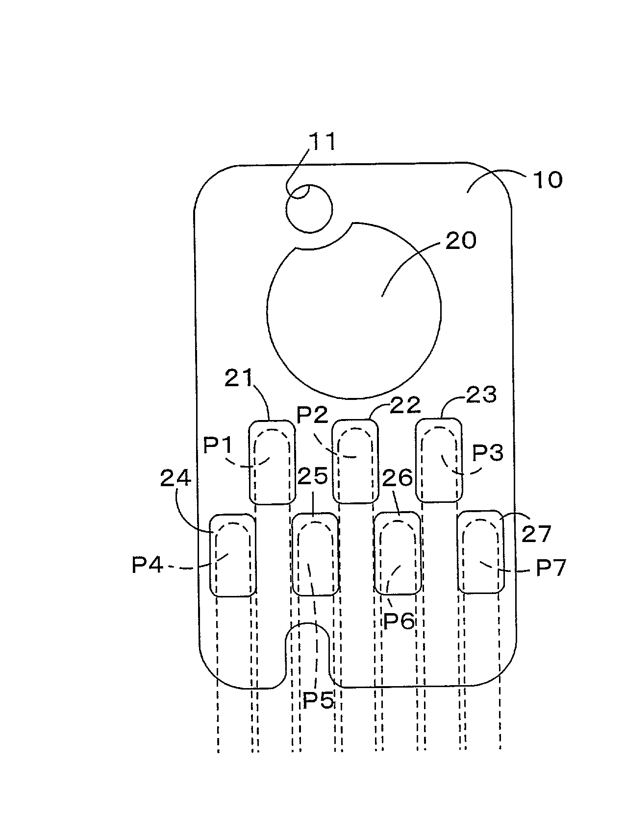
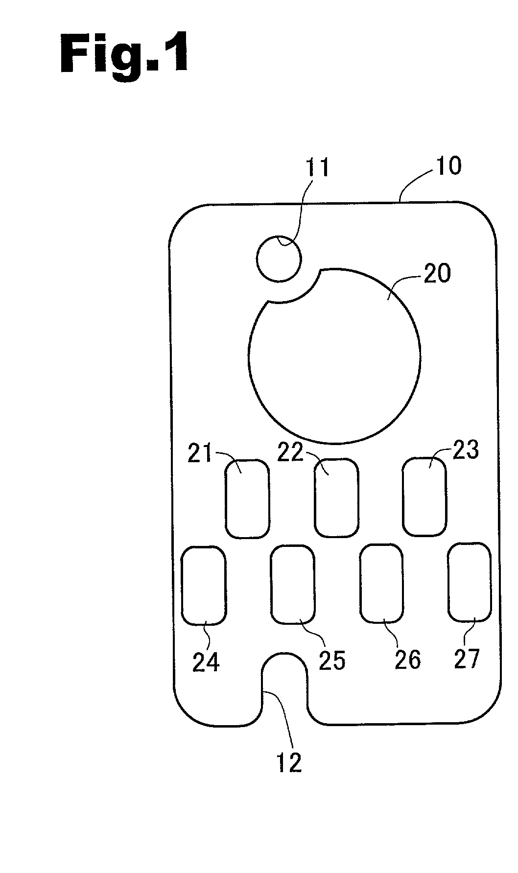
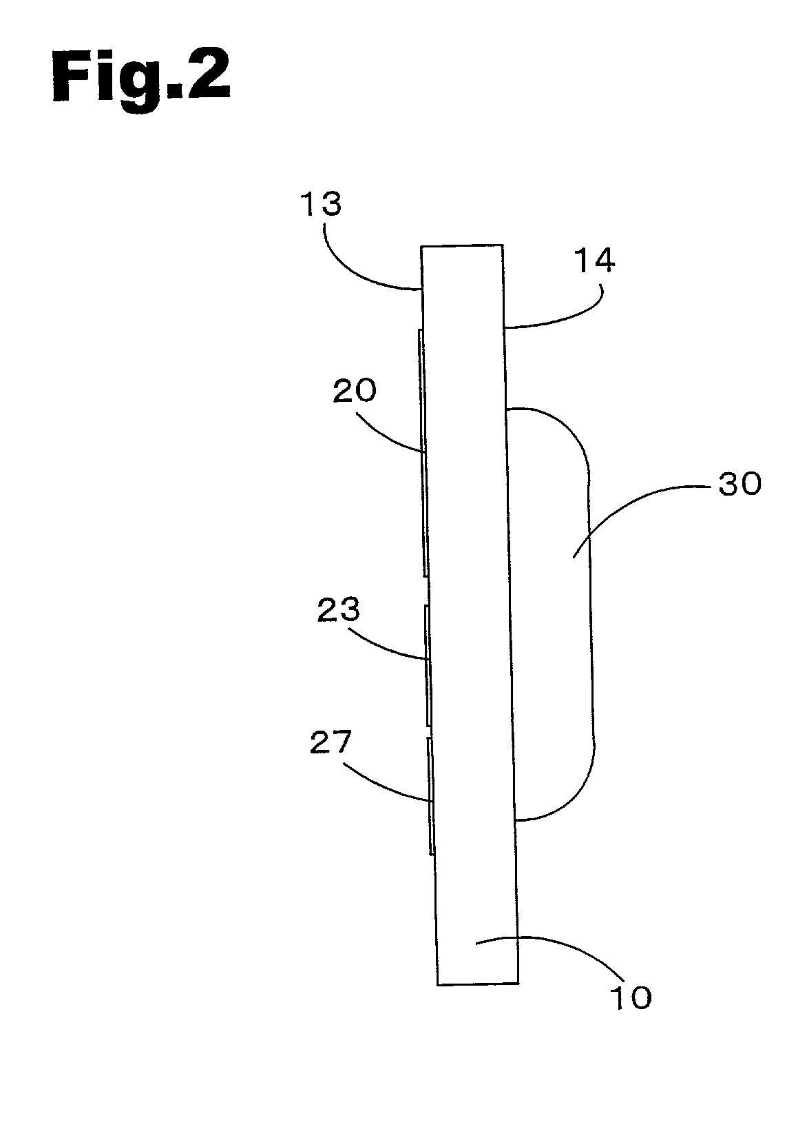
[0047] The following description of a circuit board terminal arrangement pertaining to a first embodiment makes reference to FIGS. 1-3. FIG. 1 is an illustrative diagram of an exemplary circuit board terminal arrangement pertaining to a first embodiment. FIG. 2 is a side view of the circuit board shown in FIG. 1. FIG. 3 is an illustrative diagram depicting contact of the terminals on a circuit board pertaining to a first embodiment with the contact pins of a printer.
[0048] Circuit board 10 is of substantially rectangular shape, and comprises a through-hole 11 for positioning it during ink cartridge i...
second embodiment
[0080] Accordingly, by using the circuit board 200 pertaining to the second embodiment, it is possible to accurately detect installation of the ink cartridge. It is also possible to avoid situations of an inability to access the storage device 30 despite detecting installation of the ink cartridge. Further, the clock signal CLK can be stabilized, and short-circuiting between the power supply terminal 202 and the ground terminals 204, 207 may be prevented.
[0081] The following description of a third second embodiment makes reference to FIG. 9. The circuit board 300 pertaining to the third embodiment is provided in the upper half of its juxtaposed face 13 with a substantially circular test terminal 20 used to test the storage device 30 when shipped from the factory, and in the lower half of its juxtaposed face 13 with a plurality of circular terminals 301-306, arrayed randomly. The circular terminals are, proceeding from the left in the drawing, a ground terminal 301, a read / write term...
third embodiment
[0083] Accordingly, by using the circuit board 300 pertaining to the third embodiment, it is possible to accurately detect installation of the ink cartridge. It is also possible to avoid situations of an inability to access the storage device 30 despite detecting installation of the ink cartridge. Further, short-circuiting between the power supply terminal 304 and the ground terminals 301, 306 may be prevented.
[0084] The following description of a fourth embodiment makes reference to FIG. 10. The circuit board 400 pertaining to the fourth embodiment is provided in the upper half of its juxtaposed face 13 with a substantially circular test terminal 20 used to test the storage device 30 when shipped from the factory, and in the lower half of its juxtaposed face 13 with a plurality of substantially rectangular terminals 401 to 407, arrayed in a single row. The substantially rectangular terminals are, proceeding from the left in the drawing, a ground terminal 401, a read / write terminal ...
PUM
 Abstract
Description
Claims
Application Information