Electric power supply system for a vehicle

a technology for electric power supply and vehicle, which is applied in the direction of belt control system, electric devices, windows, etc., can solve the problems of affecting other control modules, increasing the weight of the vehicle body, and deteriorating fuel mileage, so as to reduce the number of power lines, reduce the length of power lines, and reduce the weight of the vehicle

Inactive Publication Date: 2002-08-22
HITACHI LTD +1
View PDF0 Cites 25 Cited by
  • Summary
  • Abstract
  • Description
  • Claims
  • Application Information

AI Technical Summary

Benefits of technology

0018] According to this arrangement of the invention, because of the provision of an independent power line for supplying power to PCM for controlling the engine itself, which is different from the power line PL for the accessory systems, it becomes possible for PCM 20 which executes the engine control to be ensured to operate normally even if there occurs a failure in the other control modules for the accessory systems. Further, because the electrical load is supplied with power from the power line PL via the switching device that is controlled by the control module associated therewith, it becomes possible to reduce the number of power lines. Still further, because the MOS FET provided with the protective function is used as its switching device, which can prevent for the total length of the power lines from increasing due to a lengthy extension of layout of the power lines, the length of the power lines in the electric power supply system for the vehicle can be minimized.

Problems solved by technology

Any such increases in the number of power supplies and the total distance of extension of power lines, which leads to an increase in weight of the vehicle body, will deteriorate fuel mileage.
However, the prior art disclosed in the brochure of International Publication WO 96 / 26570 (1996) is associated with one problem that because every control modules are connected to a single loop power line, if a fault occurs in one of the control modules, the other control modules may be affected, and in a worst case, it becomes difficult to control the engine itself, which is an essential function for the automobile.
In order to place the plurality of fuses in one concentrated area, it becomes necessary to provide for additional power lines to connect between the plurality of fuses that are placed in one concentrated area and their associated electrical loads, consequently failing to reduce the length of the power lines.

Method used


Image

  • Electric power supply system for a vehicle
  • Electric power supply system for a vehicle
  • Electric power supply system for a vehicle

Examples


Embodiment Construction

[0105] An electric power supply system for a vehicle according to one preferred embodiment of the invention will be described, in particular, by way of example as applied to an automobile, with reference to accompanying drawings of FIGS. 1-85 in the following.

[0106] To begin with, a total system configuration of an automobile which applies an electric power supply system for a vehicle according to one preferred embodiment of the invention will be described in reference to FIG. 1.

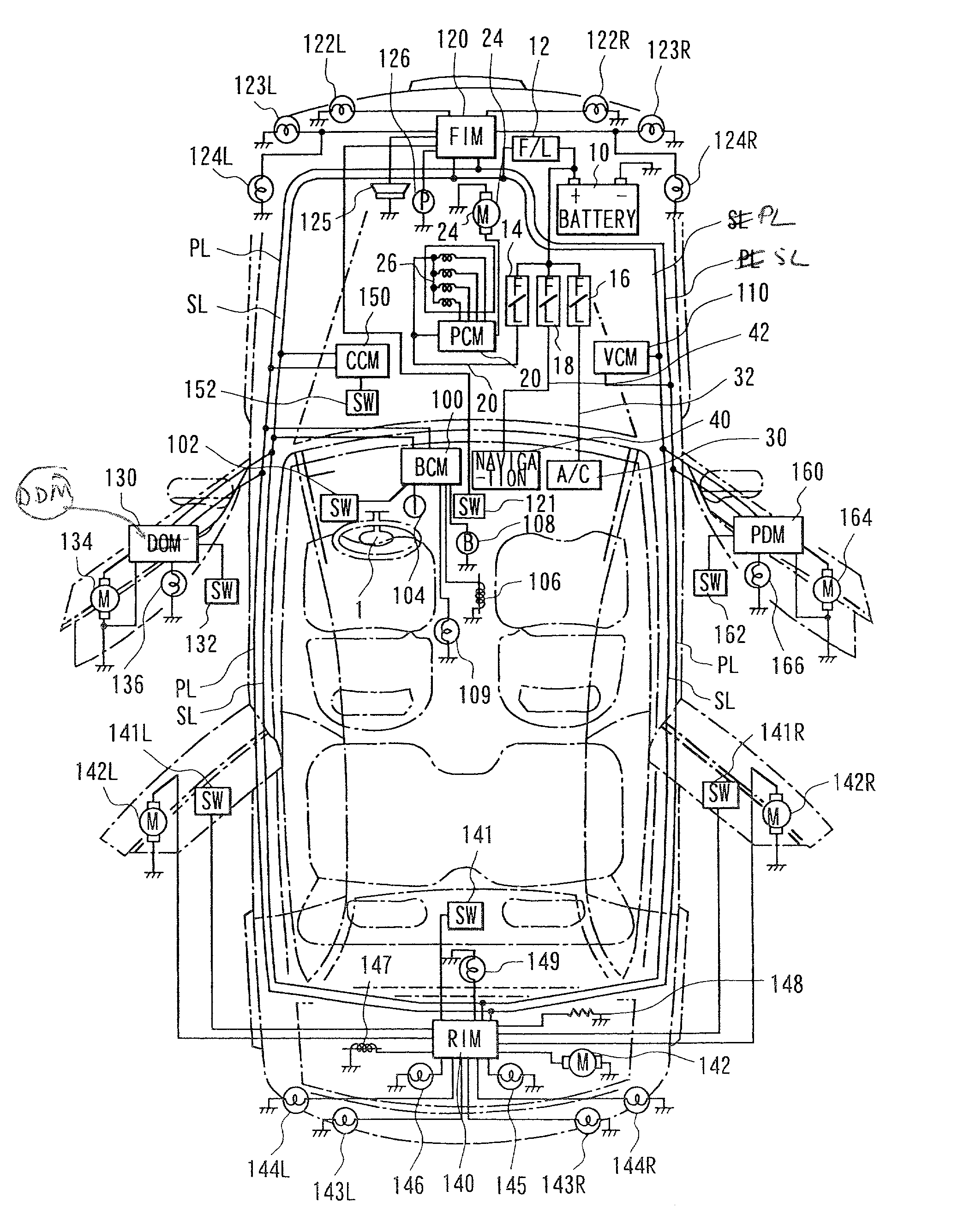
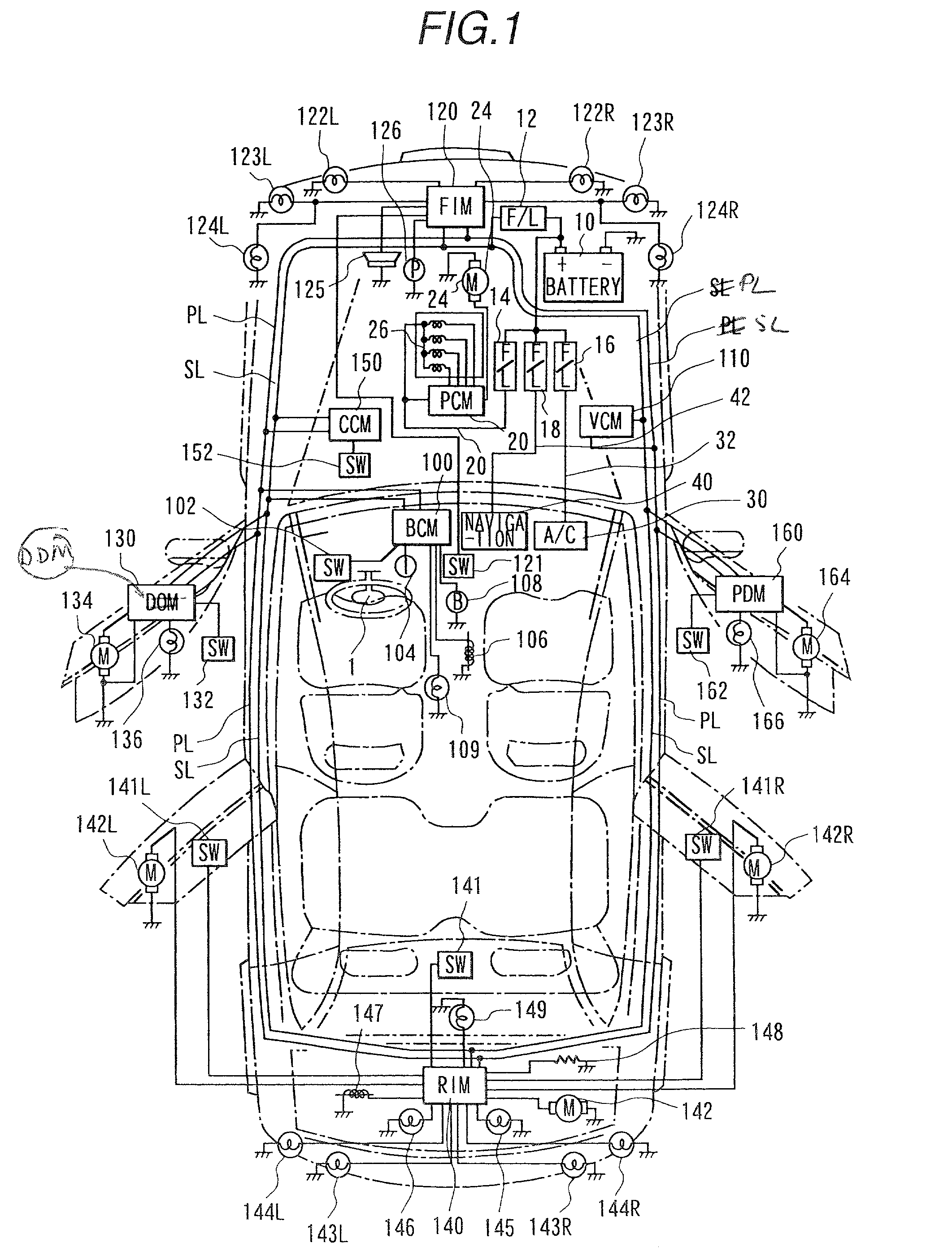
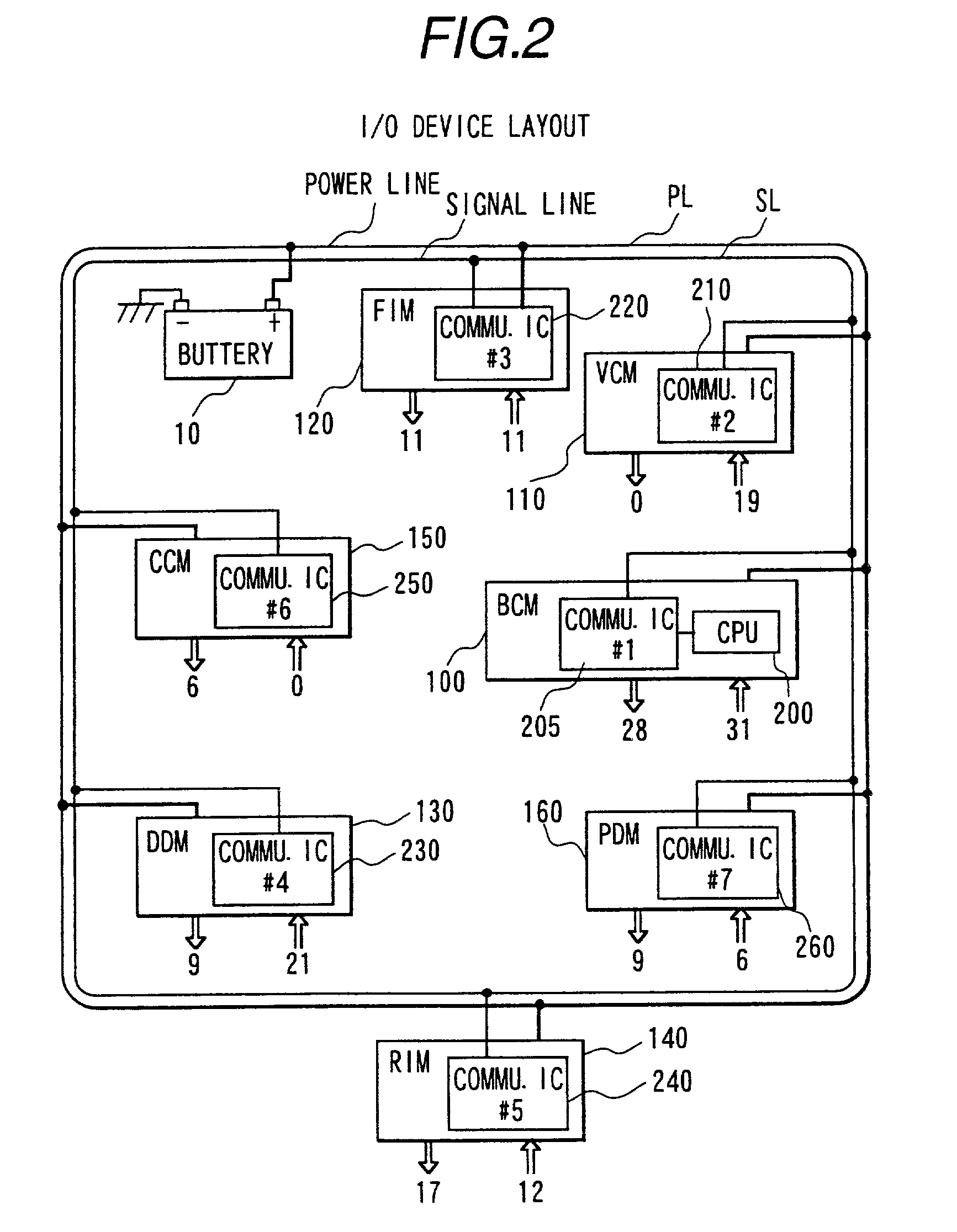
[0107] FIG. 1 is a schematic diagram indicating a system configuration of an automobile according to one embodiment of the invention.

[0108] A battery 10 is connected to a power line PL via a fusible link 12. Power line PL, which is provided in a loop of one turn circuit in an automobile, extends from a front engine room of the automobile running through a left-hand side door section, a rear section of the car and a right-hand side door section, and returns to the front engine room. To power line PL are conne...


PUM


Abstract

An electrical power supply system for a vehicle is provided, which can eliminate proliferation of adverse effect on other control modules caused within one of a plurality of control modules. This is accomplished by provision of the power supply system comprising: battery 10 for supplying power; power line PL in a loop lay-out; a plurality of control modules BCM 100, VCM 110, FIM 120, DDM 130, RIM 140, CCM 150 and PDM 160 for a plurality of accessory systems, which are connected via said power line PL in loop lay-out, wherein a power control module (PCM) 20 for controlling the engine is connected to the power supply source via another power line 22 different from the power line PL.

Description

[0001] The present invention relates to an electric power supply system for a vehicle, and particularly to an electric power supply system for use in a vehicle such as an automobile and the like, in which an electric power is supplied to electrical loads from a power supply source such as a battery for an automobile.[0002] In a conventional electric power supply for a vehicle, for example, in an electrical power supply system for an automobile, in order to supply power from a battery to its electrical loads such as lamps, motors and the like, a plurality of power lines are laid out for connecting between respective electrical loads and the battery. For a recent automobile, which has an increased number of electrical loads compared to the conventional automobile, the number of power lines has increased significantly. Further, because it is necessary to provide power lines not only for connection between respective electrical loads and the battery but also for connection between switc...

Claims


Application Information

Patent Timeline
Patent Type & Authority Applications(United States)
IPC IPC(8): B60J1/17B60R16/02B60J5/00B60Q1/04B60Q1/26B60Q1/34B60Q1/44B60Q3/02B60R1/07B60R16/023B60R16/03B60R22/48B60S1/08B60S1/58E05B83/36H02J1/06H02J7/00
CPCB60R16/03B60R16/0315H02J1/06H02J2310/46H02J7/00
Inventor SAKAMOTO, SHINICHIYOSHIDA, TATSUYAKONI, MITSURUSAITO, HIROYUKIHORIBE, KIYOSHI
Owner HITACHI LTD
Why Eureka
Try Eureka