Positive piece engagement indicator for marking tool

a positive and indicator technology, applied in the field of assembly line piece marking tools, can solve the problems of inadequate piece engagement, no impression at all, commercially available system,

Inactive Publication Date: 2002-08-22
GATTA RAYMOND P
View PDF0 Cites 67 Cited by
  • Summary
  • Abstract
  • Description
  • Claims
  • Application Information

AI Technical Summary

Benefits of technology

0031] An advantage of the present invention is that is provides verification of actual engagement between the piece to be marked and the marking tool.
0032] Another advantage of the present invention is that it provides verification of actual engagement between the piece to be marked and the marking tool in a manner adaptable to either impact type or scribe type marking systems.
0033] Yet another advantage of the present invention is that it provides a lowcost system for verifying actual engagement between the piece to be marked and the marking tool.
0034] Still another advantage of the present invention it is adaptable to providing verification of actual engagement between where the use of any metaltipped implement is to be contacted with a metal part surface.
0035] The advantages and features of the present invention will become better understood with reference to the following more detailed description and claims taken in conjunction with the accompanying drawings, in which like elements are identified with like symbols, and in which:
0036] FIG. 1 is an electrical schematic for a positive piece engagement indicator for use with a pin stamping pin impact marking tool according to the preferred embodiment of the present invention;

Problems solved by technology

Problems currently exist in the use of any currently, commercially available system that generally involve verification of the stamping or scribing process.
The main problem using either type of system is the result of inadequate piece engagement relative to the marking device.
In use of the impact type marking tools, should the impact pin fail to be properly aligned, or otherwise fail to properly collide and penetrate the surface of the metal workpiece, an inadequate impression is left, or possibly no impression at all.
Similarly, in the use of scribe type marking systems, should the scribing tip or cutting blade fail to contact the surface to be marked continuously through the etching process, the same deficient results occur.
Sundry reasons may exist that result in such errors.
Movement of the assembly line, placement of the piece on the assembly line, movement of the marking tool, rotational misalignment of the piece or marking tool, or any condition that can result in inadequate placement of the marking tool relative to the piece to be marked will cause the same overall result.
Attempts to correct for the foregoing problems have been few and limited.
Because, by necessity, each reference indica is inherently unique overall, such vision systems are complex, unreliable, and very expensive to install and operate.

Method used


Image

  • Positive piece engagement indicator for marking tool
  • Positive piece engagement indicator for marking tool
  • Positive piece engagement indicator for marking tool

Examples


Embodiment Construction

of the Figures

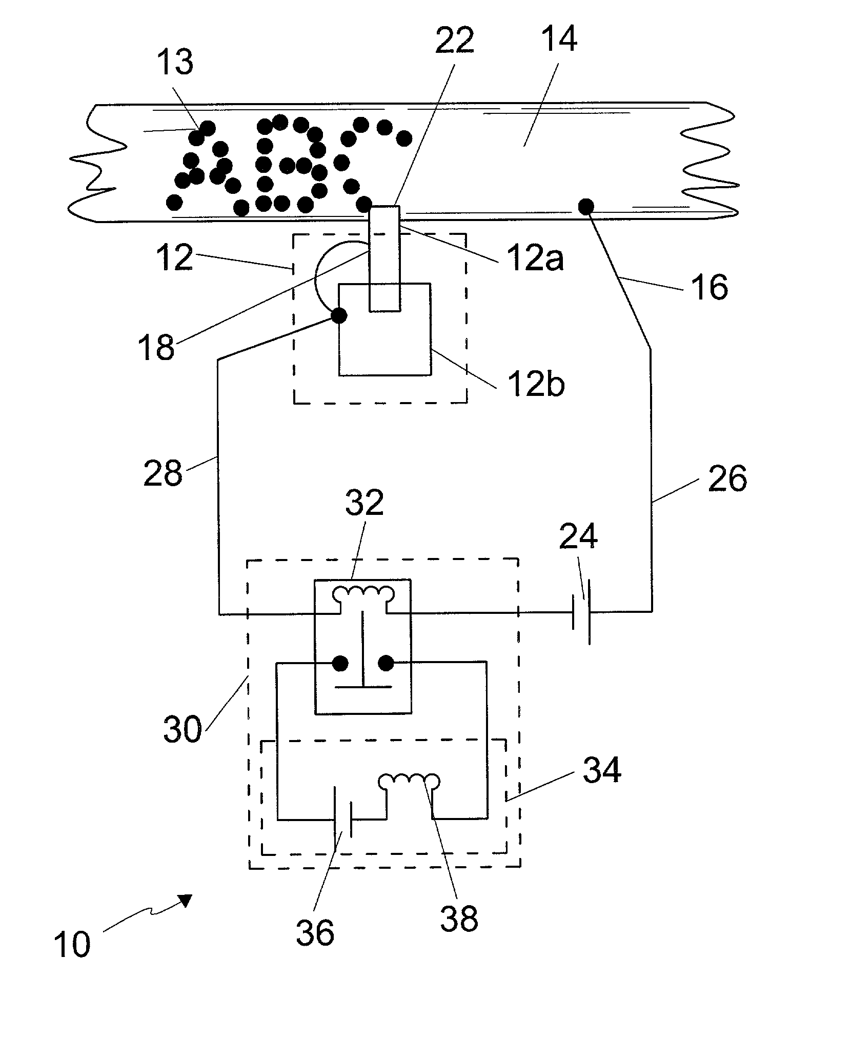
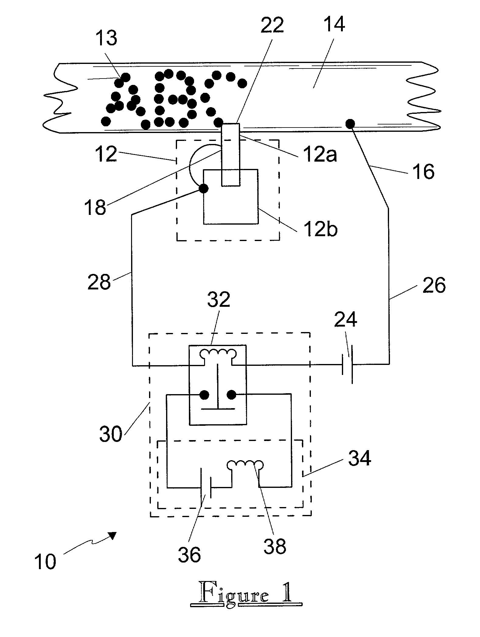
[0042] Referring now to FIG. 1, a positive piece engagement indicator 10 for use with a pin stamping pin impact marking tool 12 is shown. The pin stamping pin impact marking tool 12 is utilized as a means to imprint identifying indicia 13 within a metal piece 14. The pin stamping pin impact marking tool 12 includes an impact pin 12a thrusted into the work surface by a pin driver 12b. A metal workpiece 14, having an electrically conductive surface, is contacted with a workpiece contact probe 16. Because the workpiece may be at a varying potential due to signal noise from other equipment, or due to its physical positioning on a chain or conveyor, the contact probe 16 provides physical contact with, as well as electrical communication with the metal surface of a workpiece 14 for purposes of provided an isolated, reliable electrical circuit. The marking tool 12 is provided is in physical contacted with a marking tool contact 18 for providing physical contact with the marki...


PUM

PropertyMeasurementUnit
electrical potentialaaaaaaaaaa
physicalaaaaaaaaaa
electrical potentialaaaaaaaaaa

Abstract

A positive piece engagement indicator for marking tool is provided in which a metal workpiece is contacted with a workpiece contact probe for providing physical contact with, as well as electrical communication with the metal surface of a workpiece. A test voltage and indicator means are placed in series between the workpiece and marking tool. Upon physical contact of the marking tool engagement surface with the surface of the metal workpiece, a circuit is completed by the electrical communication there between, thereby engaging the indicator means. This allows positive verification of actual engagement of worktool to workpiece.

Description

[0001] There are no previously filed, nor currently any co-pending applications, anywhere in the world.[0002] 1. Field of the Invention[0003] The present invention relates generally to assembly line piece marking tools and, more particularly, to a positive piece engagement indicator for marking tool.[0004] 2. Description of the Related Art[0005] Current regulation require that various component assemblies that comprise a motor vehicle be scribed with a unique, identifying indicia that can allow the manufacturer or law enforcement to compare or trace the source of such component assemblies. With the current state of automation on vehicle assembly lines, such marking or scribing is also currently done, generally, in an automated fashion. For example, as a vehicle frame assembly is fabricated and conveyed down an assembly line for insertion of drive train or attachment of body or cabin components, a marking tool will scribe, etch, or stamp a unique vehicle identification number at a sp...

Claims


Application Information

Patent Timeline
Patent Type & Authority Applications(United States)
IPC IPC(8): B44B5/02
CPCB44B5/02Y10T83/086Y10T83/088Y10T83/089Y10T83/091Y10T83/141
Inventor GATTA, RAYMOND P.
Owner GATTA RAYMOND P
Why Eureka
Try Eureka