Data compression/decompression method and apparatus

a data compression and data compression technology, applied in the field of data compression/decompression methods and apparatuses, can solve the problems of increasing boot-up time, slow access to flash-proms, and inability to support data storage systems on mobile telecommunications handsets, etc., and achieves the effect of improving data compression/decompression arrangement and reducing flash-prom usag

Inactive Publication Date: 2002-08-22
SIEMENS AG
View PDF0 Cites 94 Cited by
  • Summary
  • Abstract
  • Description
  • Claims
  • Application Information

AI Technical Summary

Benefits of technology

0008] The present invention seeks to provide an improved data compression / decompression arrangement. The present invention further seeks to provide a data compression / decompression arrangement which reduces flash-PROM usage without increasing boot-up time.

Problems solved by technology

Devices such as mobile telecommunications handsets, personal digital assistants and vehicular navigation systems do not support access to data storage systems such as hard or floppy devices and their operating system and applications are typically stored on a flash-PROM that is associated with the embedded device.
Access to a flash-PROM is typically rather slow and a processor would operate at a corresponding rate if it operated by a fetching code directly from the flash-prom.
One problem is that data compression increases boot-up time.
A still further constraint imposed in system operation is that of verification: a damaged flash-PROM might change a few symbols at random and a device operating with such a flash-PROM may appear to be fully operational but would not operate correctly.
Nevertheless, these processes are not necessarily sufficiently fast for many applications, even with an optimized decompression mechanism written in, for example, assembly code.
A further complication can occur in the copying of large amounts of data in dword format, for example, since it is required that the source and destination addresses are aligned, i.e. start on an even address.

Method used


Image

  • Data compression/decompression method and apparatus
  • Data compression/decompression method and apparatus
  • Data compression/decompression method and apparatus

Examples


Embodiment Construction

[0040] There will now be described by way of example the best mode contemplated by the inventors for carrying out the invention. In the following description numerous specific details are set forth in order to provide a thorough understanding of the present invention. It will be apparent, however, to one skilled in the art, that the present invention may be practiced without using these specific details. In other instances, well known methods and structures have not been described in detail so as not to unnecessarily obscure the present invention.

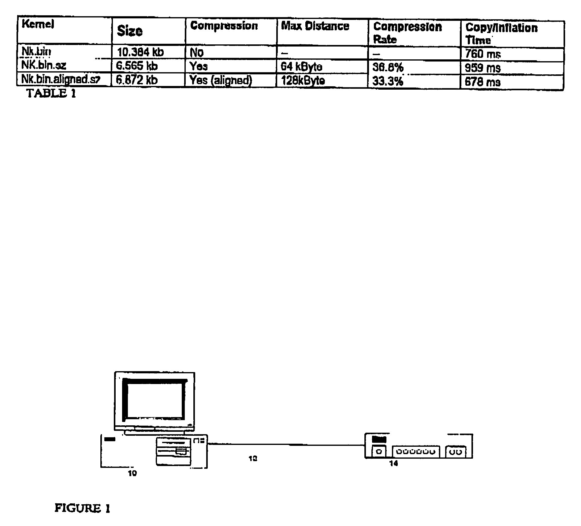
[0041] Referring now to FIG. 1, there is shown a data transfer scenario. A host computer 10 compresses data (deflation) and transmits compressed data, via a bus 12, which may be wired, optical or otherwise, to a target computer 14. The host computer compresses the file, calculates a checksum and stores the file in a hard-disk of the host computer. The target computer receives the compressed file (image) and stores the image in a flash memor...


PUM


Abstract

The present invention relates to a data compression techniques and is of particular relevance to embedded devices having a flash-prom. Data compression techniques have been known for many years. Devices such as mobile telecommunications handsets, personal digital assistants and vehicular navigation systems do not support access to data storage systems such as hard or floppy devices and their operating system and applications are typically stored on a flash-PROM that is associated with the embedded device. Flash-proms, suffer, in the main, from being rather slow. Flash-proms are also expensive. The present invention seeks to provide a data compression/decompression arrangement which can reduce flash-PROM usage without increasing boot-up time and provides a method for processing information in a data processor operable to process data to provide a sequence of uncompressed and compressed data blocks, whereby each block comprises an even number of bytes. The invention can enable a reduction in boot-up time for systems.

Description

[0001] The present invention relates to a data compression method and apparatus and, in particular, but not restricted thereto, relates to a data compression / decompression method and apparatus for embedded devices having a flash prom.BACKGROUND TO THE INVENTION[0002] An increasing number of electronic devices are being provided with embedded devices. Devices such as mobile telecommunications handsets, personal digital assistants and vehicular navigation systems do not support access to data storage systems such as hard or floppy devices and their operating system and applications are typically stored on a flash-PROM that is associated with the embedded device. Flash-proms, also known as non volatile RAM, are typically small and have the ability to retain data, even when a power supply is disconnected. The memory is also instantly erasable in blocks.[0003] Access to a flash-PROM is typically rather slow and a processor would operate at a corresponding rate if it operated by a fetchin...

Claims


Application Information

Patent Timeline
Patent Type & Authority Applications(United States)
IPC IPC(8): G06F9/44G06F9/4401G06F9/445H03M7/30
CPCG06F9/4401H03M7/3084
Inventor RADERMACHER, ANSGARSCHMITT, KLAUS JUERGEN
Owner SIEMENS AG
Why Eureka
Try Eureka