Access control system

a technology of access control system and control system, which is applied in the direction of antennas, registers, sensing record carriers, etc., can solve problems such as system malfunction, and achieve the effects of preventing errors, reducing mutual interference, and increasing the reliability of the access control system

Inactive Publication Date: 2002-08-29
TEAMAXESS TICKETING
View PDF5 Cites 27 Cited by
  • Summary
  • Abstract
  • Description
  • Claims
  • Application Information

AI Technical Summary

Benefits of technology

[0010] The present invention resolves prior art problems by connecting the terminals of the antennas associated with the access routes to a controllable deactivation device. In this way, mutual interference between several antennas and / or access routes is eliminated with the access control system of the invention, because the deactivation device places those antennas which can receive an interfering signal transmitted by another antenna in an inactive state.
[0030] Moreover, respective pairs of the scaling capacitances that can be connected or disconnected, can be connected to or disconnected from the oscillating circuit capacitance via back-to-back connected diodes and a negative and a positive auxiliary voltage. This arrangement provides a simple circuit for changing the oscillating circuit capacitance.

Problems solved by technology

Since the antennas are arranged with a relatively small separation therebetween, mutual interference can occur, which can cause the system to malfunction.

Method used


Image

  • Access control system
  • Access control system
  • Access control system

Examples


Embodiment Construction

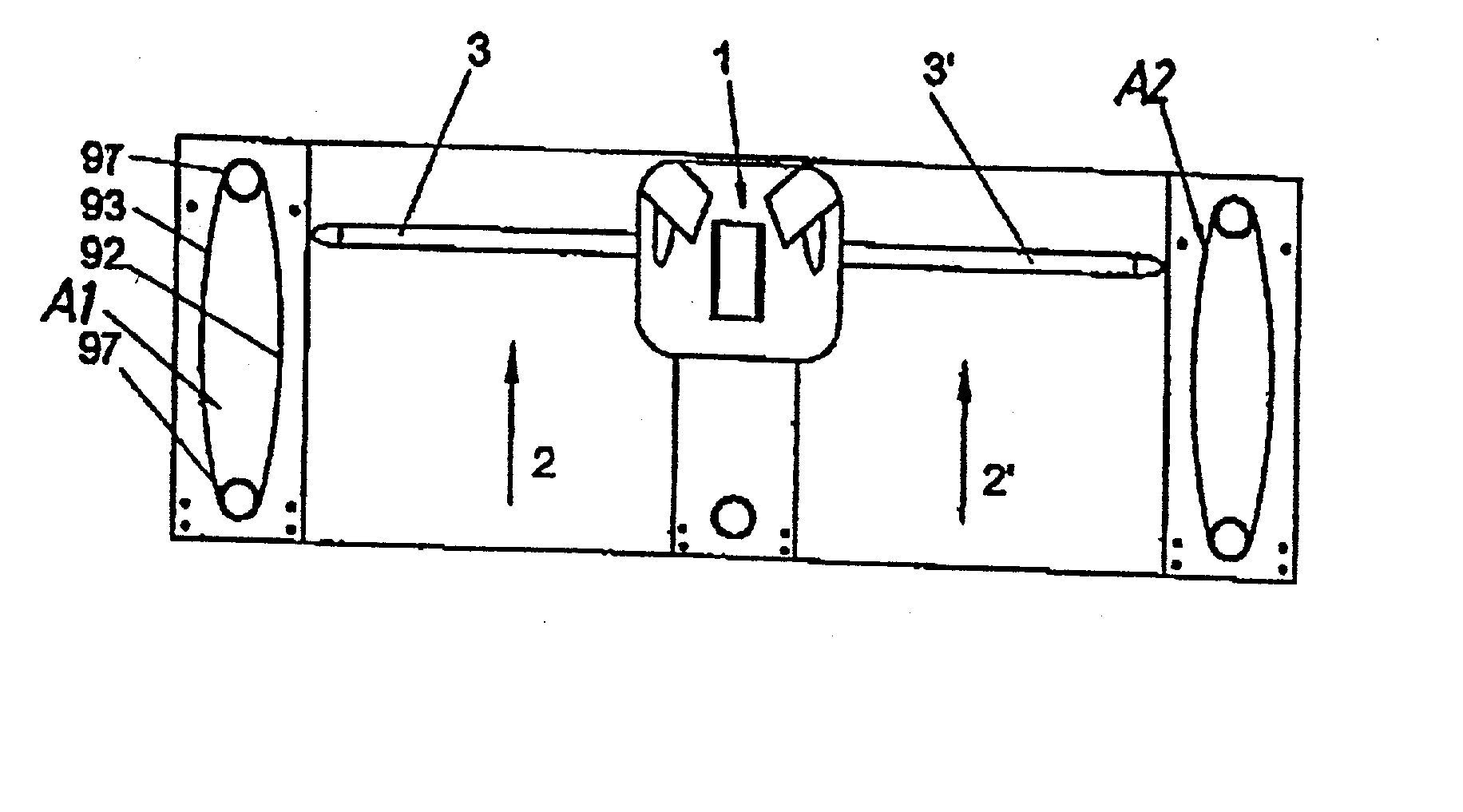
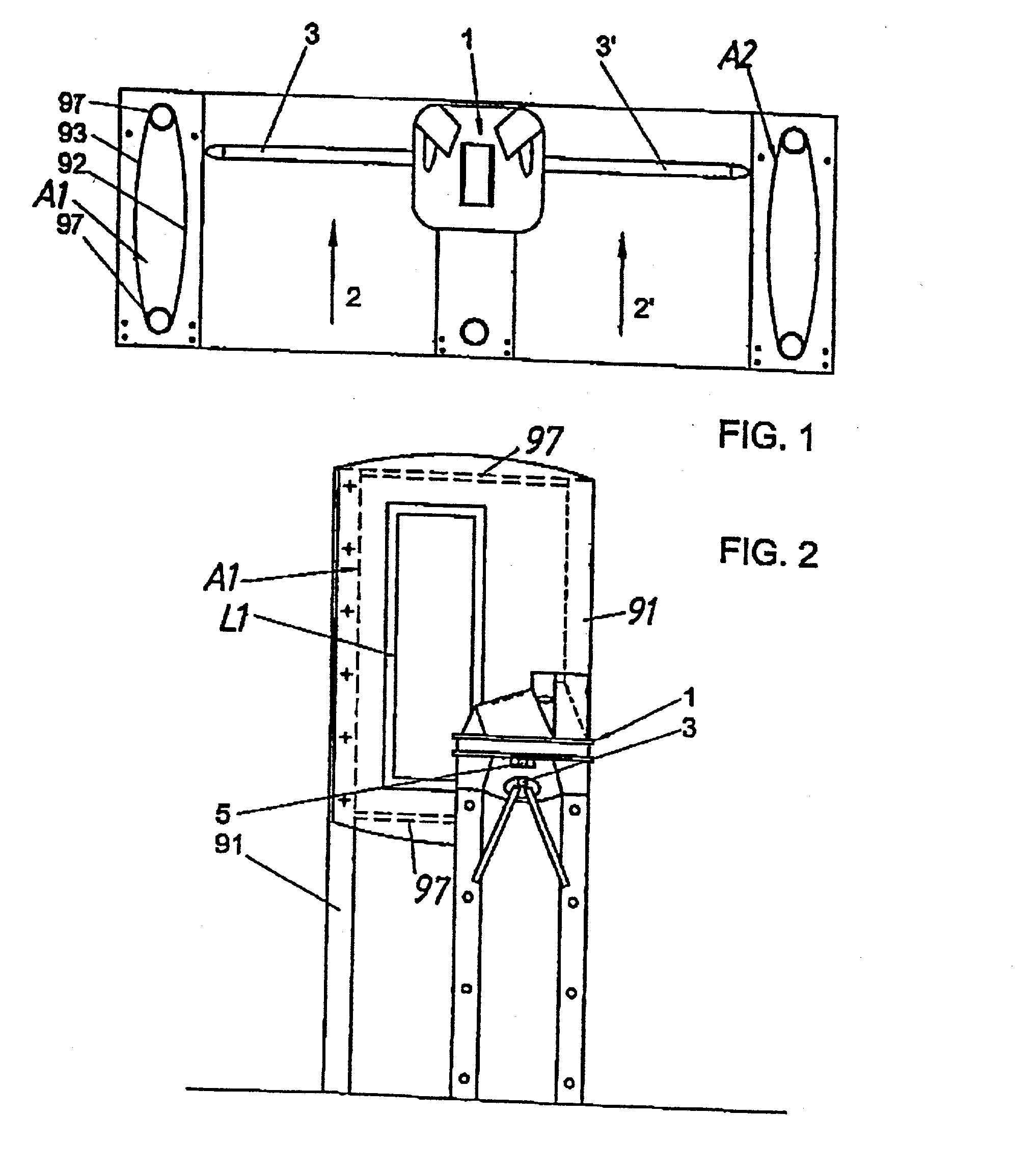
[0039] The embodiment depicted in FIGS. 1 and 2 illustrates an access control system according to the invention in use, for example, at ski resorts. However, such system can also used for other applications, for example for auditoriums, sports stadiums, swimming pools, etc. Moreover, the term access card or ticket is intended to refer to any type of ID card, ticket, card of value and the like.

[0040] FIG. 1 shows two adjacent access routes 2 and 2' which in the present example have a width between 45 cm and 65 cm. A central control device 1, which includes the components for controlling to the access control system of the invention, is located in the center between the two access routes 2, 2'. The columnar housing which houses the control device 1, forms a dividing line between the access routes 2, 2'. Each access route 2, 2' can be blocked by a turnstile 3, 3' which is opened depending on the validity of the read access authorizations. The two outer boundaries of the access routes 2...


PUM


Abstract

An access control system includes at least two access routes (2, 2') which can be blocked with controllable barriers. The access control system further includes an antenna (A1, A2) associated with each of the access routes, and a control device (1) for evaluating access authorization cards, e.g. RFID transponders, which operate without making galvanic contact. Each antenna (A1, A2) is connected to a corresponding transmit / receive unit (13, 14), and the terminals of the antennae (A1, A2) associated with the access routes (2, 2') are connected to a deactivation device.

Description

CROSS-REFERENCES TO RELATED APPLICATIONS[0001] This application is a continuation of prior filed copending PCT International application no. PCT / AT00 / 00253, filed Sep. 22, 2000.[0002] This application claims the priority of Austrian Patent Application Serial No. GM 650 / 99, filed Sep. 22, 1999, pursuant to 35 U.S.C. 119(a)-(d), the subject matter of which is incorporated herein by reference.BACKGROUND OF THE INVENTION[0003] The present invention relates to an access control system with at least two access routes that can preferably be blocked with controllable barriers, with an antenna being allocated to each of the access routes, and a control device for evaluating access authorization cards, e.g. RFID transponders, which operate without making galvanic contact. Each antenna is connected to a corresponding transmit / receive unit.[0004] Systems for access control are known, for example, for use in aerial tramways and lifts, but can also be used in many other applications. Typically, a...

Claims


Application Information

Patent Timeline
Patent Type & Authority Applications(United States)
IPC IPC(8): G06K7/08G07C9/00G07C9/02H01Q1/22H01Q1/52H01Q7/00
CPCG06K7/10336G07C9/00111G07C9/02H01Q1/22H01Q1/2216H01Q1/521H01Q7/00G07C9/10G07C9/28
Inventor KOCZNAR, WOLFRAMGOLSER, RUDOLFFISCHER, JOSEFHELLER, HANS-PETER
Owner TEAMAXESS TICKETING
Why Eureka
Try Eureka