
Optical assembly

a technology of optical assembly and assembly assembly, which is applied in the direction of hose connection, paper/cardboard container, instruments, etc., can solve the problems of deteriorating the alignment between the members, affecting the assembly process, and affecting the alignment of the aligning apparatus, so as to achieve the effect of easy and effective assembly

Inactive Publication Date: 2002-09-05
HON HAI PRECISION IND CO LTD
View PDF0 Cites 5 Cited by
  • Summary
  • Abstract
  • Description
  • Claims
  • Application Information

AI Technical Summary

Benefits of technology

[0013] In view of above described problems of the prior art, it is an object of the present invention to provide an optical assembly which can be assembled easily and effectively.

Problems solved by technology

This complicates the assembling process of the optical assembly.
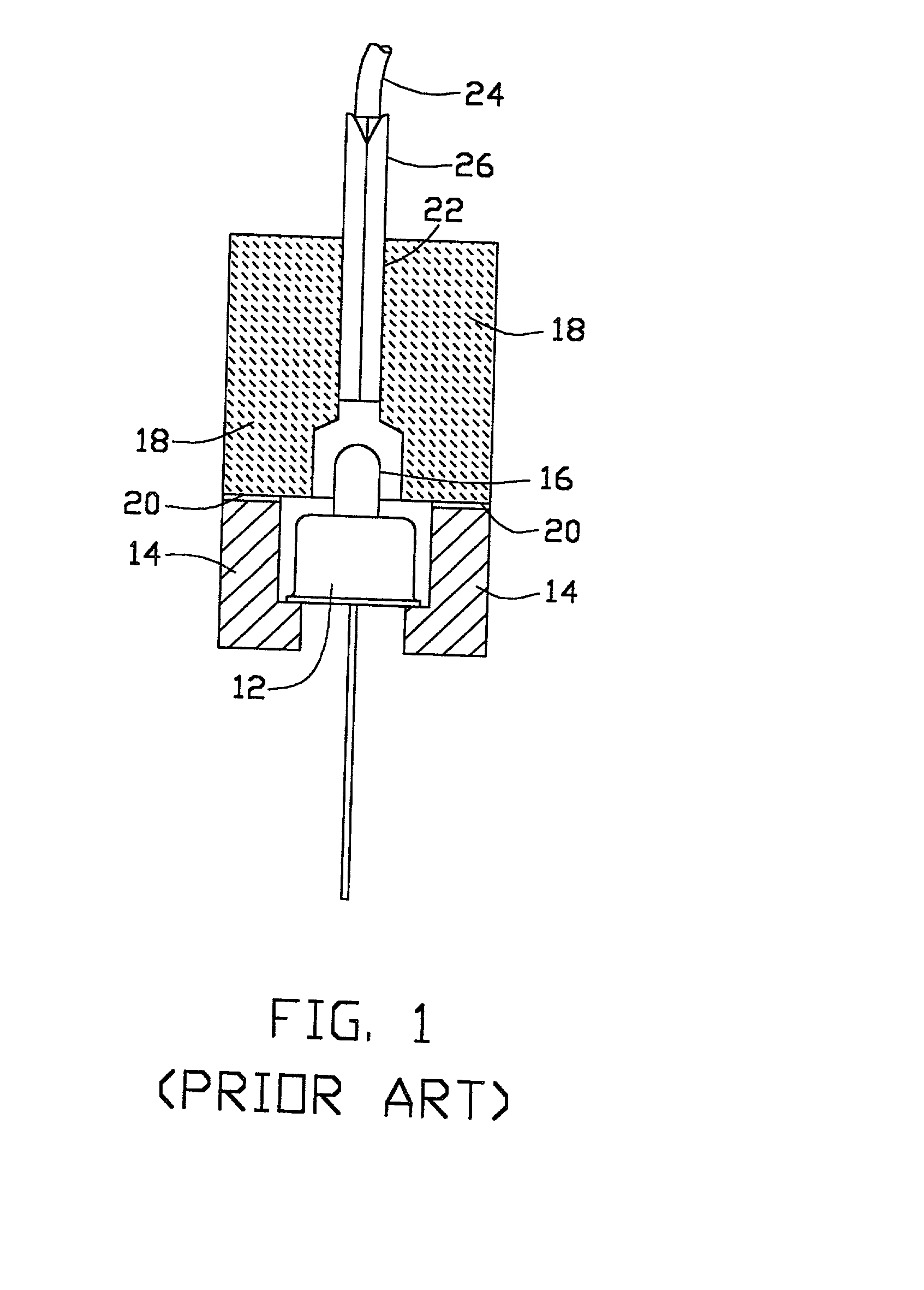
Since it is difficult to have a uniform heating result on the members, the members may displace with respect to each other during the heating process, deteriorating the alignment between the members.
Furthermore, unexpected contacts or impacts may occur on the aligning apparatus when it is moved into the heating oven.
Such contact or impact may cause misalignment between the members.
Besides the above drawbacks, this method is not suitable for single-mode fiber transmission system.
This limits the selection of the material.
This increases the cost of design and manufacture.
The cost for performing laser welding is high.
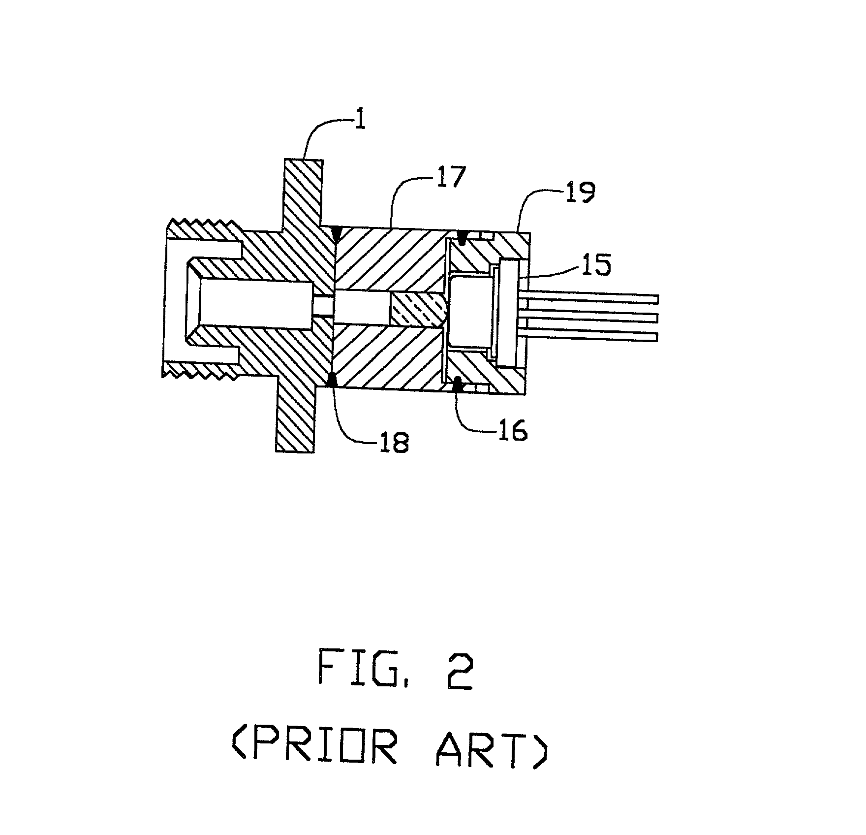
The method suffers a non-uniform curing result of the glue because the glue is cured by being contacted with steam and it is hard to control the distribution of steam in a given space.
This may cause displacements of the members with respect to each other, resulting in misalignment.

Method used


Image

  • Optical assembly
  • Optical assembly
  • Optical assembly

Examples


Embodiment Construction

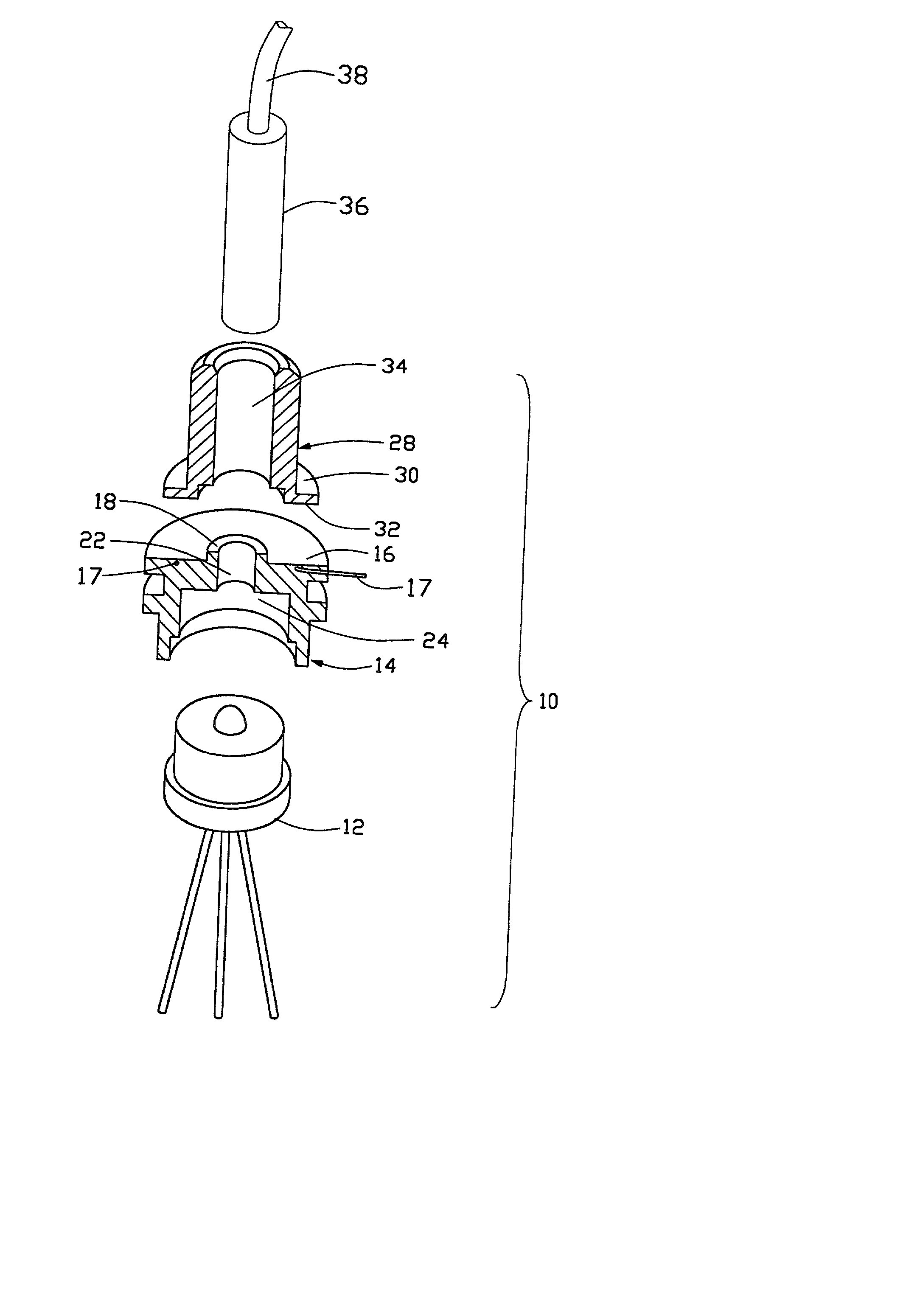
[0020] Referring to FIGS. 3 and 4, there is shown an optical assembly according to the present invention. The optical assembly comprises a light source 12, a support member 14, a receptacle 28 and a ferrule 36 retaining an optical fiber 38. The light source 12, such as a laser diode (LD) or a light emitting diode (LED), is fixedly received and contained in a cavity 24 defined in the support member 14.

[0021] The support member 14 is made of plastic, having a first junction surface 16. The support member 14 forms a cylindrical projection 18 on the first junction surface 16 in which an aperture 22 is defined. The aperture 22 is in communication with the cavity 14 and is preferably perpendicular to the first junction surface 16.

[0022] The receptacle 28 has a circumferential flange 30 forming a second junction surface 32. The receptacle 28 is attached to the support member 14 with the second junction surface 32 positioned on the first junction surface 16 of the support member 14. A bore ...


PUM

PropertyMeasurementUnit
diameteraaaaaaaaaa
poweraaaaaaaaaa
junction surfaceaaaaaaaaaa

Abstract

An optical assembly includes a light source, a support member and a receptacle. The support member is made of plastic, forming a first junction surface. The light source is contained in the support member. The receptacle is made of metal or plastic forming a second junction surface. The receptacle is attached to the support member with the second junction surface positioned on the first junction surface. A resistance wire is positioned in the support member surrounding the aperture and proximate the first junction surface. Two terminals of the wire extend outside the support member for being coupled to an external power source. To assemble the optical assembly, the receptacle and the support member are mounted in an aligning apparatus which operates to adjust the relative position between the receptacle and the support member. After adjusting to have the members in perfect alignment, a heat cured epoxy is applied between the surfaces, power is then supplied to the resistance wire to heat and cure the epoxy and thus securing the receptacle to the support member.

Description

[0001] 1. Field of the Invention[0002] The present invention relates to an optical assembly and more specifically to a transceiver assembly which is used for receiving or transmitting optical signals.[0003] 2. The Related Art[0004] An optical transceiver module is an important part of an optical communication system. The optical transceiver requires an optical assembly for receiving or transmitting optical signals. The optical assembly consists of many parts which must have precise relative orientation with respect to each other. This complicates the assembling process of the optical assembly. Thus a variety of methods have been developed for manufacturing the optical assembly.[0005] Heat cured epoxy is one of the methods for assembling the optical assembly. The optical assembly includes a support member and a cap member, wherein the support member has a first surface, and the cap member has a corresponding and matching second surface. To assemble, the cap member and the support mem...

Claims


Application Information

Patent Timeline
Patent Type & Authority Applications(United States)
IPC IPC(8): G02B6/42
CPCG02B6/4225G02B6/4239Y10T156/10
Inventor WANG, CHUNG YUNGCHANG, HUNG LUNWANG, HSIANG-JUI
Owner HON HAI PRECISION IND CO LTD
Learn More