

Compound coaxial cable stripping tool
- Summary
- Abstract
- Description
- Claims
- Application Information
AI Technical Summary
Benefits of technology
Problems solved by technology
Method used
Image

Examples
Embodiment Construction
)
[0044] In describing the preferred embodiment of the present invention, reference will be made herein to FIGS. 1-9 of the drawings in which like numerals refer to like features of the invention.
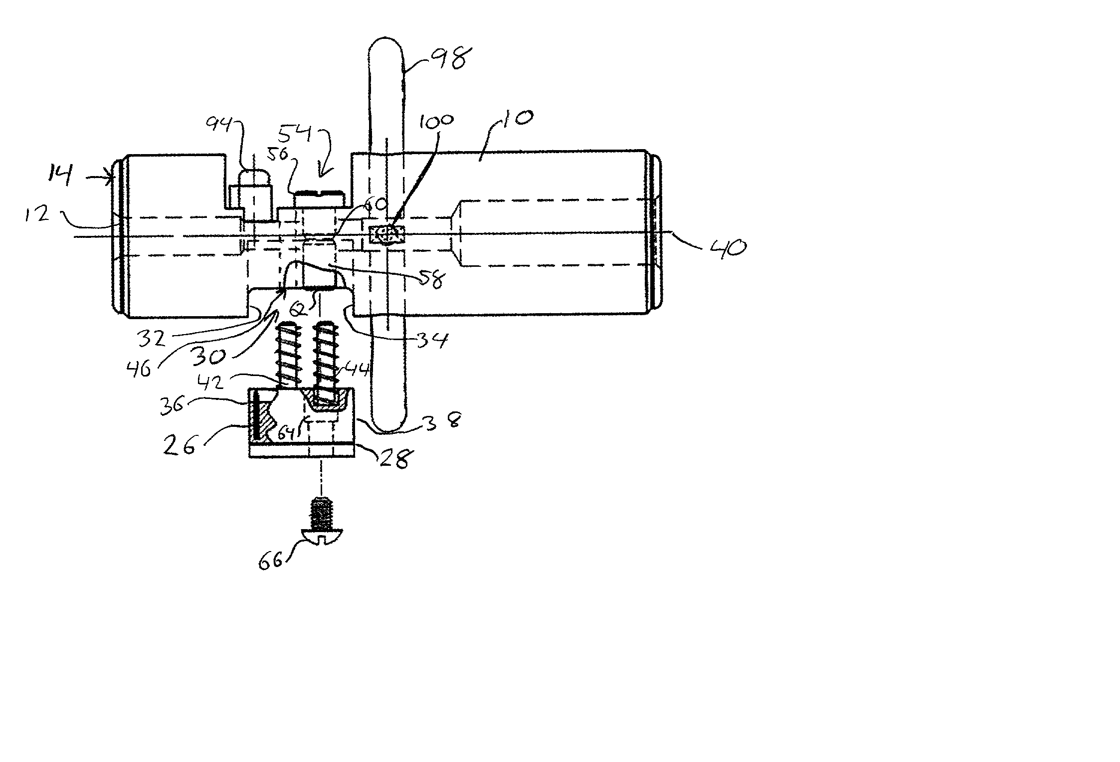
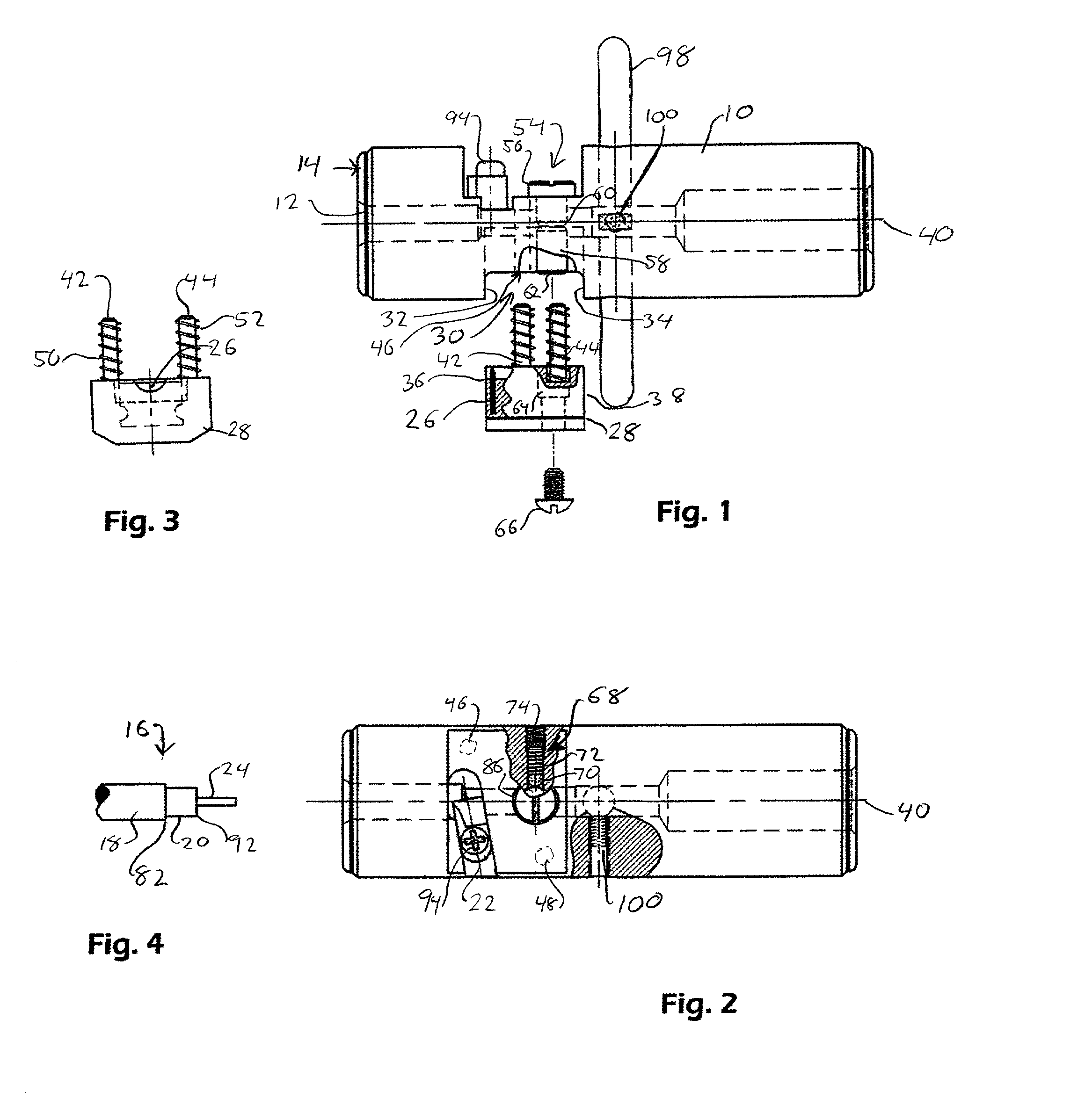
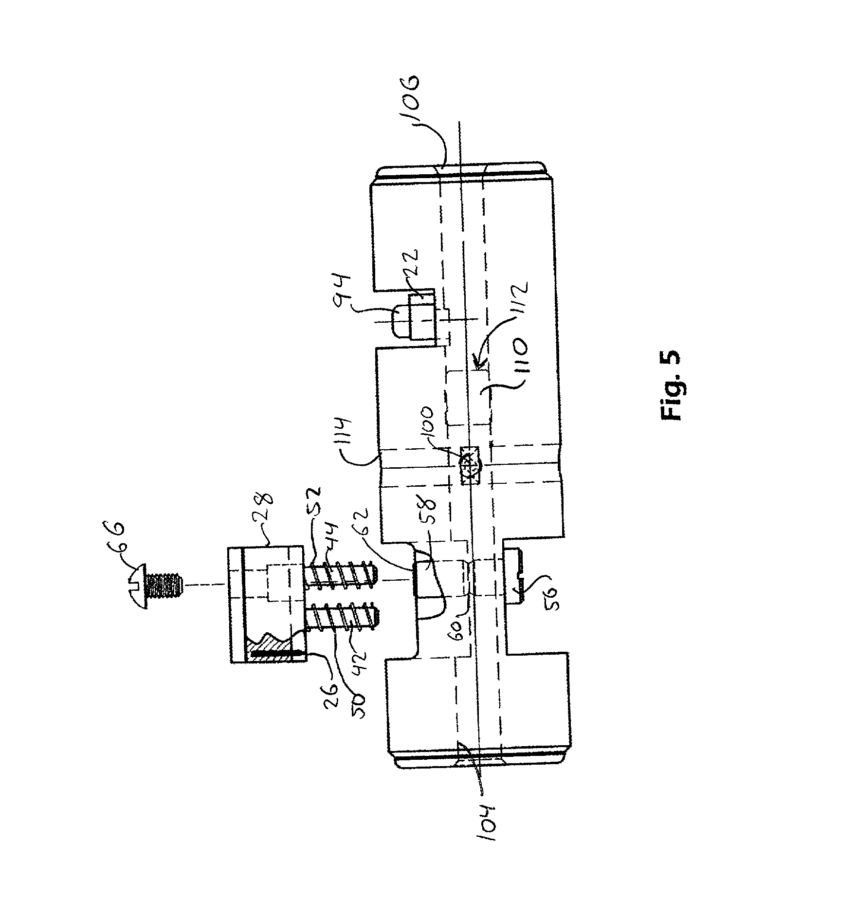
[0045] Referring to FIG. 1, the coaxial cable stripping tool of the present invention includes a cylindrical tool body 10 having an axial opening 12 in end 14 of the tool body. As can be seen in FIG. 4, which shows a completed stripping cut, the tool is designed to produce a stepped cut on coaxial cable 16. The coaxial cable includes an outer jacket 18 having an outside diameter just slightly smaller than the inside diameter of axial opening 12, allowing the cable to smoothly enter axial opening 12 where it is supported by the inner walls during cutting.
[0046] As the tool is rotated relative to the cable, outer conductor 20 is exposed by a double-edged cutting blade 22 (see FIG. 2), which removes only the outer jacket 18. The cut required to expose inner conductor 24 is made by a planar cutt...
PUM
 Abstract
Description
Claims
Application Information