High efficiency ion exchange system for removing arsenic from water

a technology of arsenic and ion exchange system, which is applied in the direction of moving filter element filter, filtration separation, separation process, etc., can solve the problems of large vessel size, increased operation and maintenance costs, and large valve size, and achieves easy maintenance, high process efficiency, and reduced waste water

Inactive Publication Date: 2002-09-12
HSBC BANK
View PDF0 Cites 10 Cited by
  • Summary
  • Abstract
  • Description
  • Claims
  • Application Information

AI Technical Summary

Benefits of technology

[0027] A particular advantage of the invention is its ability to provide treated water with a markedly reduced amount of waste water being produced.
[0028] We now have devised a fixed bed system for ion exchange removal of arsenic from water which embodies the advantages of a moving bed system without the size and cost of a moving bed design. The present design involves employing a substantial plurality (at least ten and preferably from about ten to about twenty-five) of fixed bed vessels which do not move but which can be accessed by the various process flows using a series of controller-actuatable valves, for example microprocessor-controlled valves. The system uses closely clustered, fixed position, multiple vessels combined with valves and piping so arranged to obtain the cost advantages of using small mass-produced vessels and valves, and a combination of easily maintained valves.
[0029] The present invention achieves (1) high process efficiency, (2) process flexibility, (3) low wastewater production, and (4) construction compactness and maintenance ease.
[0030] The invention uses several relatively small diameter fixed vessels each with two ports, one on each opposite end. These ports are closely associated with small volume headers. These headers are connected to manifolds used to conduct the process fluids to and from the vessels. A nest of small, easily-accessible process control valves is mounted between the headers and the manifolds.
[0031] Thus, in one aspect this invention is embodied as a system for continuously removing arsenic and other contaminants from arsenic contaminated water. This system includes a plurality of immobile vessels, each containing a resin bed capable of binding the contaminants from the contaminated water and yielding purified water and a contaminated resin bed. The vessels each have a first fluid communication opening (port) at a first end and a second fluid communication opening at a second end. The resin bed is located between the two ports.
[0032] Each vessel has two headers directly adjacent to the two ports. These headers are connected to the ports with a minimum of dead volume. Each of the headers is directly connected through automatically-actuatabl-e valves to a series of manifolds which supply the various process feeds and accept the various process products.

Problems solved by technology

In many cases, the water may also contain contaminants that are known to be detrimental to health.
Such ionic substances as nitrite, nitrate, arsenic, antimony, fluoride, selenate, chromate, perchlorate and other similar harmful substances are often found.
There are disadvantages, however, because larger vessels and large valves are required.
Operation and maintenance costs will rise when first equipment costs are low because of large vessels.
This step requires time and process water and produces additional waste water.
These systems eliminate the use of large vessels and the subsequent high maintenance and replacement costs.
Consequently, as the platform rotates, the process stream entering and leaving any of the vessels changes according to a predetermined and difficult to alter process flow, set by the multiport valves.
In many cases, the disposal of waste is a major cost of operation and becomes most important when operation over several years is considered.
Another disadvantage of the fixed bed system is the large number of heavy and bulky automatic valves needed to control the process flows through each vessel and the use of large diameter vessels.
The main disadvantage of the moving bed system is that it requires two to three times the space and also requires very large and complex specialized multi port valves and a complex plumbing design.
The net result is a far more costly system--approximately three times the cost of its fixed bed counterpart.
Another disadvantage of the moving bed system is its inherent mechanical instability.
This design is subject to relatively small earthquake forces.
Steel girder supports are often required to enhance stability, but cost increases.

Method used


Image

  • High efficiency ion exchange system for removing arsenic from water
  • High efficiency ion exchange system for removing arsenic from water
  • High efficiency ion exchange system for removing arsenic from water

Examples


first embodiment

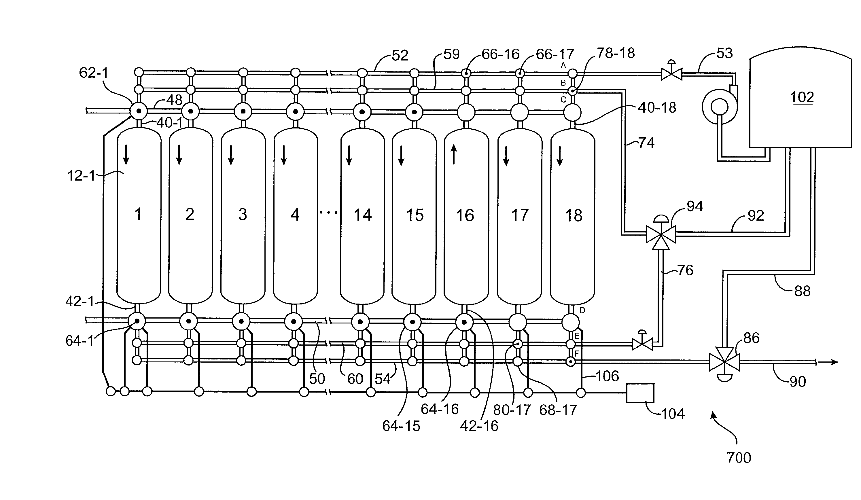
[0091] the overall system of the invention is shown in FIG. 7 as system 700. System 700 includes eighteen vessels 12-1 through 12-18, where eighteen is a representative number in the range of ten to twenty-five or greater. Each vessel is numbered with an identifier "1", "2" . . . "18 " to identify its unique position in the overall system. Each vessel is configured for cocurrent flow of treatment water and regenerant essentially as set out in FIG. 5 and is equipped with headers, manifolds, lines and valves as described with reference to FIGS. 4 and 5. These elements are numbered in accord with the numbering used in FIGS. 4 and 5 with an added indication if a particular element is associated with a particular vessel. For example, header "40-1" is the "40" header associated with vessel 1.

[0092] Each of the eighteen vessels contains a bed of ion exchange resin and each has a header 40-1, etc which provides access to the vessel and to contaminated water supplied by feed manifold 48, via...

second embodiment

[0105] the overall system of the invention is shown in FIG. 8 as system 800. System 800 includes sixteen vessels 12-1 through 12-16. The numbering of elements of the process is in accord with the numbering used with FIG. 7. Arsenic-contaminated water is feeding through the resin beds in vessels 12-1 through 12-13. Purified water is being withdrawn from these thirteen vessels through headers 42-1 and valve 64-1, etc and collected in manifold 50 for use. Again, valves 64-1 through 64-13 all are shown with a dot to show a positive fluid flow.

[0106] Vessels 12-14 through 12-16 are not in service removing arsenic and purifying water. The resin beds in vessels 12-15 and 16 are undergoing regeneration with a brine solution and the bed in vessel 12-14 is being rinsed to remove spent brine prior to being returned to service. As noted above, this regeneration could be carried out with substantial volumes of regenerant and rinse going to waste but such a process would be undesirable for waste ...

example 1

Arsenic Removal

[0157] The system of the invention is useful for removing arsenic from water. An overall process is illustrated in FIG. 13.

[0158] The ion exchange unit was substantially in accord with system 800 in FIGS. 8 and 13. Since this was a test system, the number of vessels was reduced to six, three in absorption, two in regeneration and one in rinse. In a commercial scale unit, additional vessels would be present in service in absorption for a total of at least 10 vessels. The beds were each 36 inches in diameter and about 48 inches deep. Treated water was removed via line 136.

[0159] The water being treated was fed through line 130 to oxidizer 132 and had the following representative composition.

1 Anions 2.93 mg / L Ca 20.00 mg / L Cl 7.60 mg / L Mg 13.00 mg / L Mn 79.00 mg / L NO.sub.3 1.00 mg / L K 24.00 mg / L Na 22.00 mg / L As V 0.012 mg / L As III 0.011 mg / L

[0160] This water feed was treated with chlorine (0.2 mg / L) (0.2 ppm) to oxidize the AsIII to AsV. Any equivalent oxidizer, such as...


PUM

PropertyMeasurementUnit
diameteraaaaaaaaaa
depthaaaaaaaaaa
depthaaaaaaaaaa

Abstract

The disclosed invention is a fixed bed ion exchange system from removing arsenic from water. It employs a combination of electronically controlled process steps and specific systems configurations to duplicate the effects of moving resin beds from one operating position to another as is required in moving bed ion exchange water purification systems. The invention combines features of single fixed bed ion exchange systems with those of a moving bed system.

Description

[0001] This invention relates to ion exchange systems for removing arsenic from water. More particularly it relates to fixed bed ion exchange systems for removing arsenic which are configured to yield the flexibility and efficiency of moving bed systems.BACKGROUND AND STATE OF THE ART[0002] Ion exchange is a chemical process often used to separate certain contaminant substances from a drinking water supply containing a mixture of several other harmless dissolved substances. For example, common ground water used for drinking water will contain substances such as the ionic forms of calcium, magnesium, sulfate, chloride and bicarbonate. In many cases, the water may also contain contaminants that are known to be detrimental to health. Such ionic substances as nitrite, nitrate, arsenic, antimony, fluoride, selenate, chromate, perchlorate and other similar harmful substances are often found. It is desirable to separate out the contaminants harmful to health by treating the water with an i...

Claims


Application Information

Patent Timeline
Patent Type & Authority Applications(United States)
IPC IPC(8): B01J47/14B01J49/00C02F1/00C02F1/42C02F1/72C02F1/76
CPCB01J47/14B01J49/0004B01J49/0095C02F1/008C02F1/42C02F1/72C02F1/76C02F2101/10C02F2101/103C02F2101/12C02F2101/16C02F2101/163C02F2101/22C02F2209/005C02F2303/16Y10S210/912Y10S210/913Y10S210/903Y10S210/902B01J49/05B01J49/85
Inventor JENSEN, PETER L.GUTER, GERALD A.ZIOL, DAN
Owner HSBC BANK
Why Eureka
Try Eureka