Flying vehicle of inverse sustentation (FVIS)

a technology of inverse sustentation and flying vehicle, which is applied in the direction of vertical landing/take-off aircraft, aircraft navigation control, air-cushion, etc., can solve the problems of airplane inclination, inconvenience, design limitations, etc., and achieve good cargo bay capacity , the effect of reducing the size of the aircra

Inactive Publication Date: 2002-09-12
SALAS AMERICO
View PDF0 Cites 20 Cited by
  • Summary
  • Abstract
  • Description
  • Claims
  • Application Information

AI Technical Summary

Problems solved by technology

This makes the airplane elevate, with the inconvenience that it requires to move horizontally to reach the speed of sustentation and its sustentation force.
However, the helicopter, for its limitations on design, doesn't have good capacity in the cargo bay, because the screw propellers are not big enough for sustentation (as it is in the airplane).
Moreover, its speed is not the same as the airplane, since the rotation of the main screw propeller, when advancing, cannot lean too much without losing sustentation.
However, since these vehicles require a mattress of air between the helmet and the water or floor, they are only able to rise to a small height.
The well-known British airplane of vertical takeoff "British Sea Harrier...

Method used


Image

  • Flying vehicle of inverse sustentation (FVIS)
  • Flying vehicle of inverse sustentation (FVIS)
  • Flying vehicle of inverse sustentation (FVIS)

Examples


Embodiment Construction

.

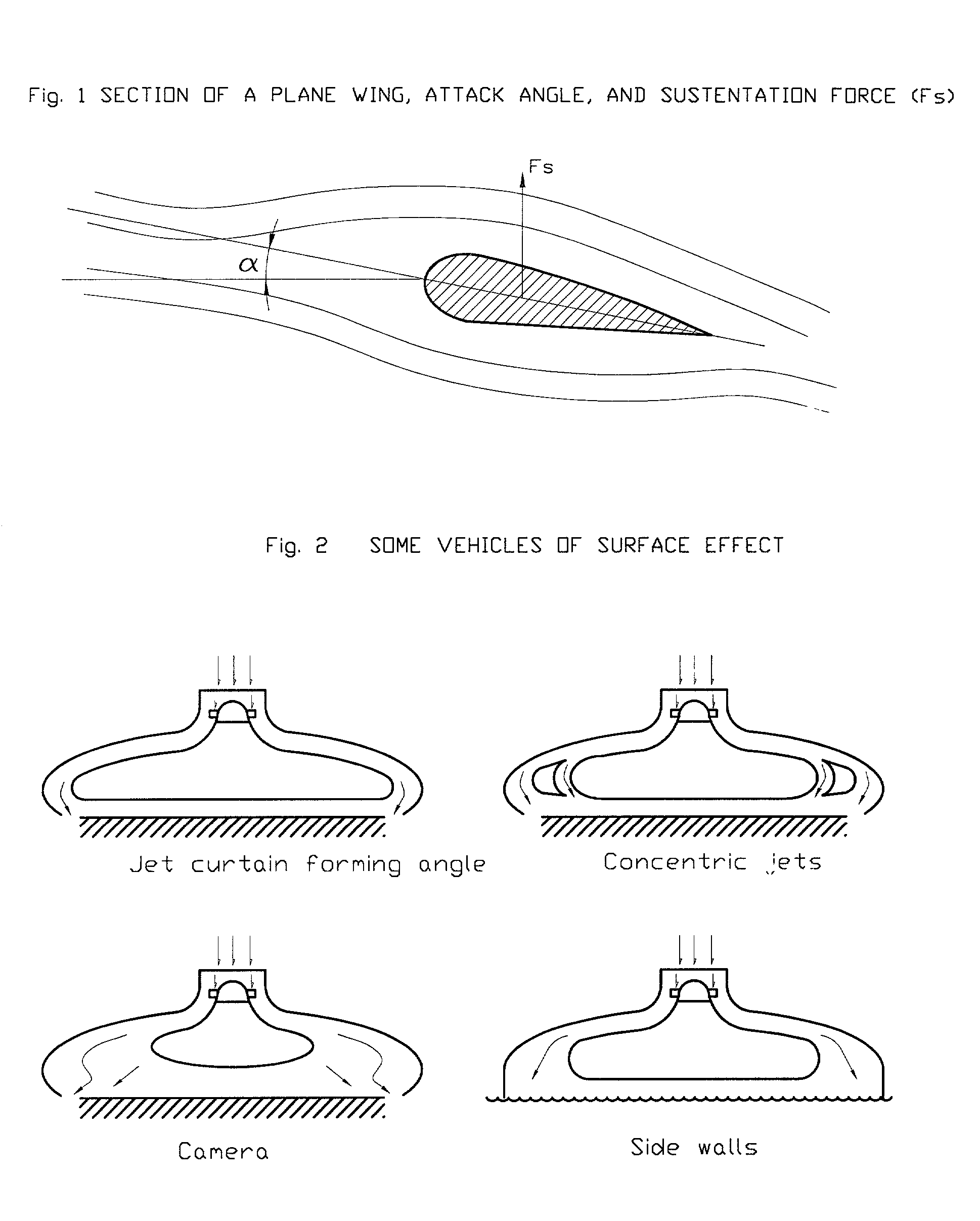
[0105] The Flying Vehicle of Inverse Sustentation (FVIS) is an air transport unit for passengers and cargo. It has vertical takeoff, due to a central airflow or gas escape directed radially toward a stable circular wing with regard to this flow by means of a duct designed for this purpose. The vehicle consists in general of the following main parts:

[0106] The flow generating plant or main unit which can be:
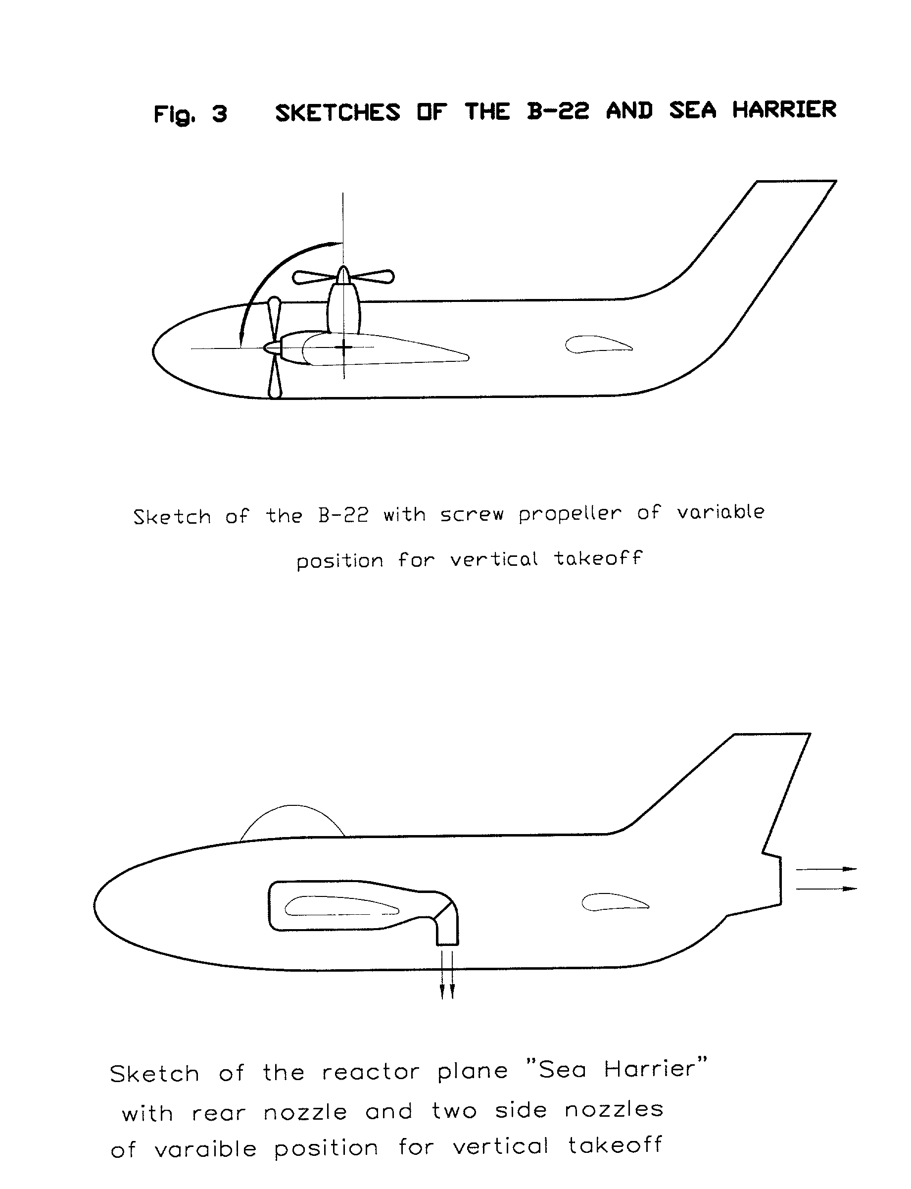
[0107] A jet engine

[0108] An aeronautical motor of internal combustion and a screw propeller

[0109] A jet engine and a screw propeller

[0110] An air admission duct

[0111] An exit duct

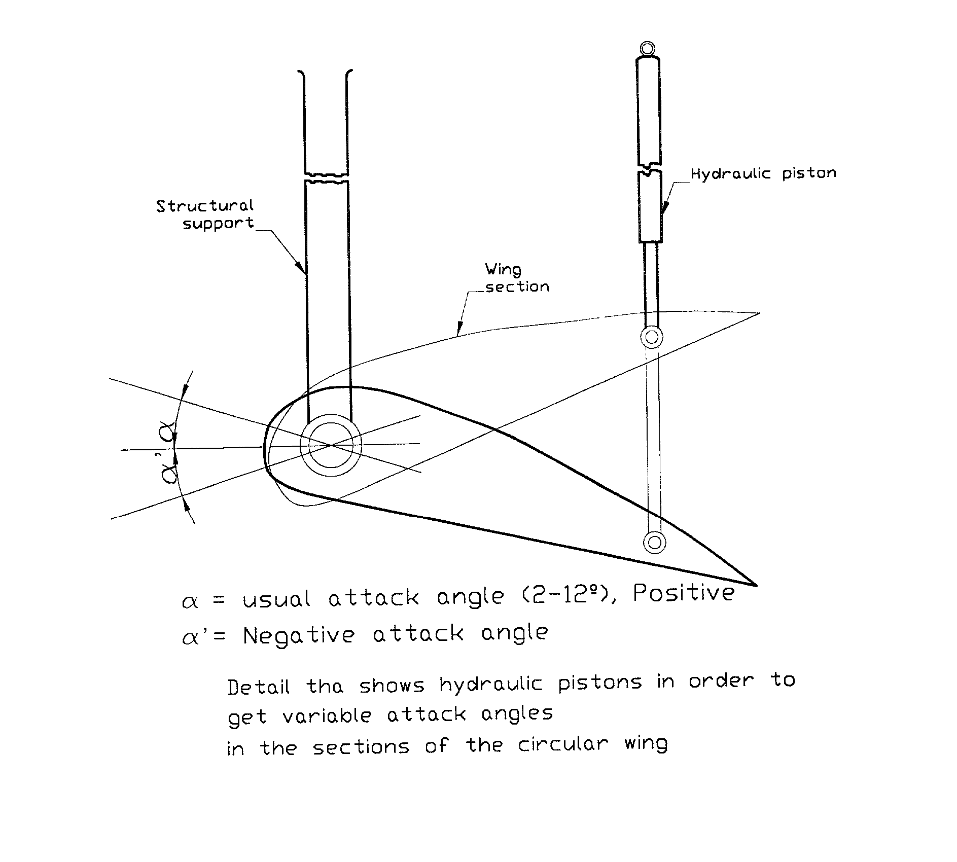
[0112] A circular wing

[0113] A main circular unitary axis

[0114] A protective cover

[0115] The secondary unit of propulsion

[0116] A tail steering wheel (when necessary)

[0117] A cockpit

[0118] Accessories (generator, electric motors, valves, fuel tank, bomb of fuel, accumulator, hydraulic bomb, hydraulic pistons)

[0119] A cockpit of optional inferior maneuver

[0120] To obtain the main flow of sustentation can...


PUM


Abstract

The Flying Vehicle of Inverse Sustentation (FVIS) is an air transport unit for passengers and cargo. The vehicle has vertical takeoff due to a main flow-generating unit which generates combustion gases that are directed toward a circled firm wing, to obtain the necessary sustentation to elevate the vehicle. The flow directed toward the wing is protected with a cover with the surrounding means. The horizontal displacement is obtained using secondary propulsion units.

Description

CROSSED REFERENCES TO RELATED APPLICATIONS[0001] Not applicable.INFORM CONCERNING TO THE INVESTIGATION OR DEVELOPMENT FEDERALLY SPONSORED[0002] Not applicable.REFERENCE TO THE APPENDIX OF MICROFICHE[0003] Not applicable.ANTECEDENTS OF THE INVENTION[0004] The field of this invention is the aeronautics. Beginning with the principle of airplane flights, they can elevate because of the action of the displacement of the vehicle whose wings, when impacted on the atmospheric air, generate current lines on and under the wing, producing a mass concentration difference of air between both sides. This way, a sustentation force of vertical direction going up, elevates the vehicle.[0005] This effect is possible because of the form of the wing, with a wider border in the superior part, and an attack angle that is given by the wing regarding a horizontal plane. (FIG. 1) This produces the separation of the air in current lines with more concentration in the inferior part of the wing. This makes the...

Claims


Application Information

Patent Timeline
IPC IPC(8): B60V1/02B64C29/00B64C39/06B64D25/12
CPCB60V1/02B64C29/0025B64C39/064B64D25/12
Inventor SALAS, AMERICO
Owner SALAS AMERICO
Why Eureka
Try Eureka