Environmental barrier material for organic light emitting device and method of making

Inactive Publication Date: 2002-09-12
SAMSUNG DISPLAY CO LTD
View PDF0 Cites 212 Cited by
  • Summary
  • Abstract
  • Description
  • Claims
  • Application Information

AI Technical Summary

Benefits of technology

0012] The encapsulated organic light emitting device can have an oxygen transmission rate through the at least one first barrier stack of less than 0.005 cc/m.sup.2/day at 23.degree. C. and 0% relative humidity, an oxygen transmission rate through the at least

Problems solved by technology

Light emitting diodes (LEDs) and liquid crystal displays (LCDs) have found many useful applications, but they are not adequate for all situations.
The use of OLEDs in flat panel displays and other information display formats is limited by the poor environmental stability of the devices. G. Gustafson, Y. Cao, G. M. Treacy, F. Klavetter, N. Colaneri, and A. J. Heeger, Nature, Vol. 35, Jun. 11, 1992, pages 477-479.
Humidity and oxygen significantly reduce the useful life of most OLEDs.
Furthermore, saran cannot be deposited using flash evaporation, condensation, and in situ polymerization within a vacuum chamber.

Method used


Image

  • Environmental barrier material for organic light emitting device and method of making
  • Environmental barrier material for organic light emitting device and method of making

Examples


Embodiment Construction

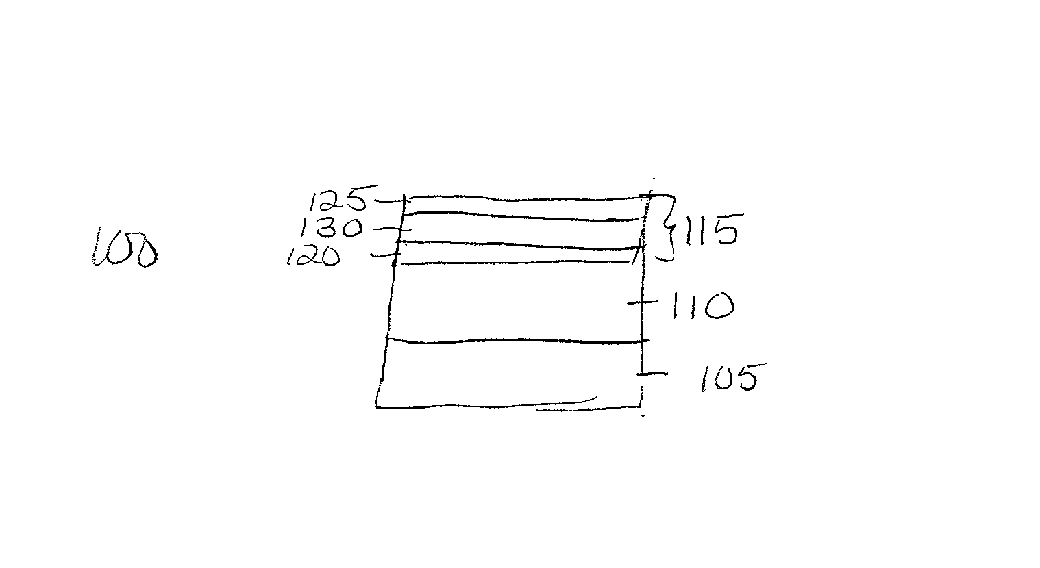
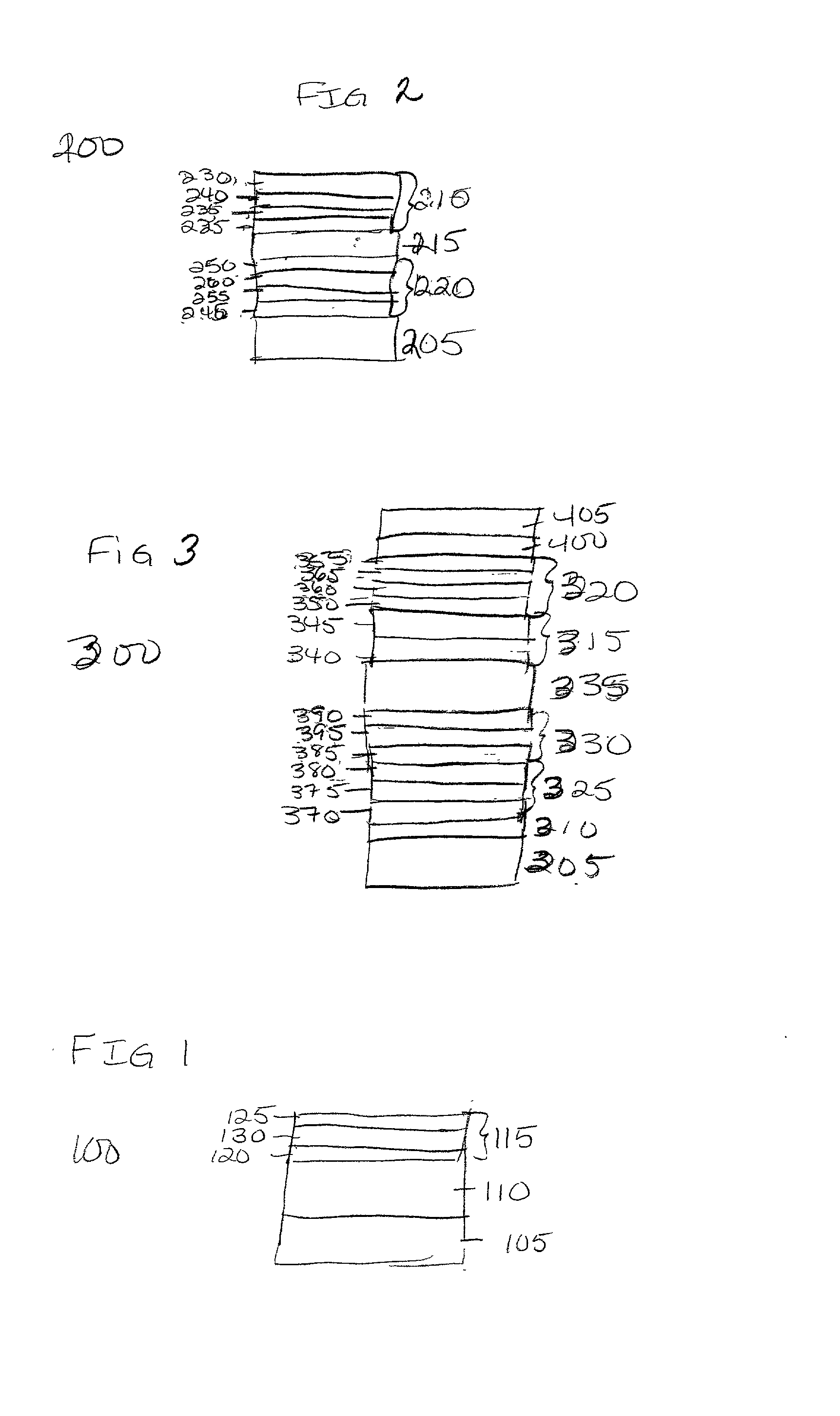
[0026] One embodiment of the present invention is shown in FIG. 1. The encapsulated OLED 100 includes a substrate 105, and organic light emitting device 110, and a first barrier stack 115. First barrier stack 115 includes first decoupling layers 120, 125 and first barrier layer 130. The organic light emitting device 110 is encapsulated between the substrate 105 and the first barrier stack 115.

[0027] Although FIG. 1 shows a barrier stack with decoupling layers on both sides of a barrier layer, the barrier stacks can have one or more decoupling layers and one or more barrier layers. There could be one decoupling layer and one barrier layer, there could be multiple decoupling layers on one side of one or more barrier layers, or there could be one or more decoupling layers on both sides of one or more barrier layers. The first layer of the barrier stack can be either the decoupling layer or the barrier layer, and the last layer can be either. The important feature is that the barrier st...


PUM


Abstract

An encapsulated organic light emitting device. The device may include a substrate, an organic light emitting layer stack adjacent to the substrate, and at least one first barrier stack adjacent to the organic light emitting device, the at least one first barrier stack comprising at least one first barrier layer and at least one first decoupling layer wherein the at least one first barrier stack encapsulates the organic light emitting device. There may be a second barrier stack adjacent to the substrate and located between the substrate and the organic light emitting device. The second barrier stack has at least one second barrier layer and at least one second decoupling layer. A method of making the encapsulated organic light emitting device is also provided.

Description

BACKGROUND OF THE INVENTION[0001] This application is a continuation-in-part of U.S. patent application Ser. No. 09 / 427,138, filed Oct. 25, 1999 entitled "Environmental Barrier Material for Organic Light Emitting Device and Method of Making" which is a continuation-in-part of U.S. patent application Ser. No. 09 / 212,779, filed Dec. 16, 1998 entitled "Environmental Barrier Material for Organic Light Emitting Device and Method of Making."[0002] The present invention relates to organic light emitting devices (OLEDs), and more particularly to OLEDs encapsulated in barrier stacks.[0003] There is a need for versatile visual displays for electronic products of many different types. Light emitting diodes (LEDs) and liquid crystal displays (LCDs) have found many useful applications, but they are not adequate for all situations. OLEDs are a relatively new type of visual display which has shown great promise. An OLED basically includes an organic electroluminescent substance placed between two ...

Claims


Application Information

Patent Timeline
IPC IPC(8): H05B33/04B32B7/02B32B9/00H01L51/50H01L51/52H01M2/08H05B33/02H05B33/10
CPCH01L51/5256H01L2251/5338H01M2/08Y02E60/10H10K2102/311H10K59/8731H10K50/8445
Inventor GRAFF, GORDON L.GROSS, MARK E.AFFINITO, JOHN D.SHI, MING-KUNHALL, MICHAEL G.MAST, ERIC S.WALTY, ROBERTRUTHERFORD, NICOLEBURROWS, PAUL E.MARTIN, PETER M.
Owner SAMSUNG DISPLAY CO LTD
Why Eureka
Try Eureka