
Tone generation controlling system

Inactive Publication Date: 2002-09-12
YAMAHA CORP
View PDF0 Cites 25 Cited by
  • Summary
  • Abstract
  • Description
  • Claims
  • Application Information

AI Technical Summary

Benefits of technology

[0004] In view of the problems and limitations of the related art outlined above, it is an object of the present invention to provide a tone control virtual instrument system which is both easy to use and able to produce complicated and sophisticated music. More specifically, it is an object of the present invention to provide a system by which it is possible to produce such music by the use of hand movements.
[0005] To this end, the present inventors have concentrated their efforts on developing a tone control virtual instrument system which utilizes hand movements. The reason for using a hand as an instrument of movement in such a system is that a hand can be moved with relative ease and flexibility within three dimensions, and is less vulnerable to tiredness or strain, than, for example, an arm.
[0010] In the tone control system of the present invention, tone attributes of an actual musical instrument being played can be controlled on the basis of an arrangement of the musical instrument. Thus, a user while playing an instrument can easily change tone attributes of the instrument by changing the angle of inclination of the instrument along a vertical or horizontal plane.

Problems solved by technology

However, a problem of the system of the related art is that it is neither sufficiently accurate nor sensitive to enable a subtle range of control of tones generated.
Specifically, in the prior art, body movements detected by sensors are limited to a relatively small number of patterns, with tones or effects generated by such movements being controlled by relatively simple parameters.
Due to these limitations, using the system of the related art it is difficult to produce music which is complicated, or sophisticated or subtle in effect.
The result is a system which while allowing the generation of more complex music does so at the expense of both convenience and ease of use.

Method used


Image

  • Tone generation controlling system
  • Tone generation controlling system
  • Tone generation controlling system

Examples


first embodiment

A. FIRST EMBODIMENT

A-1. Configuration

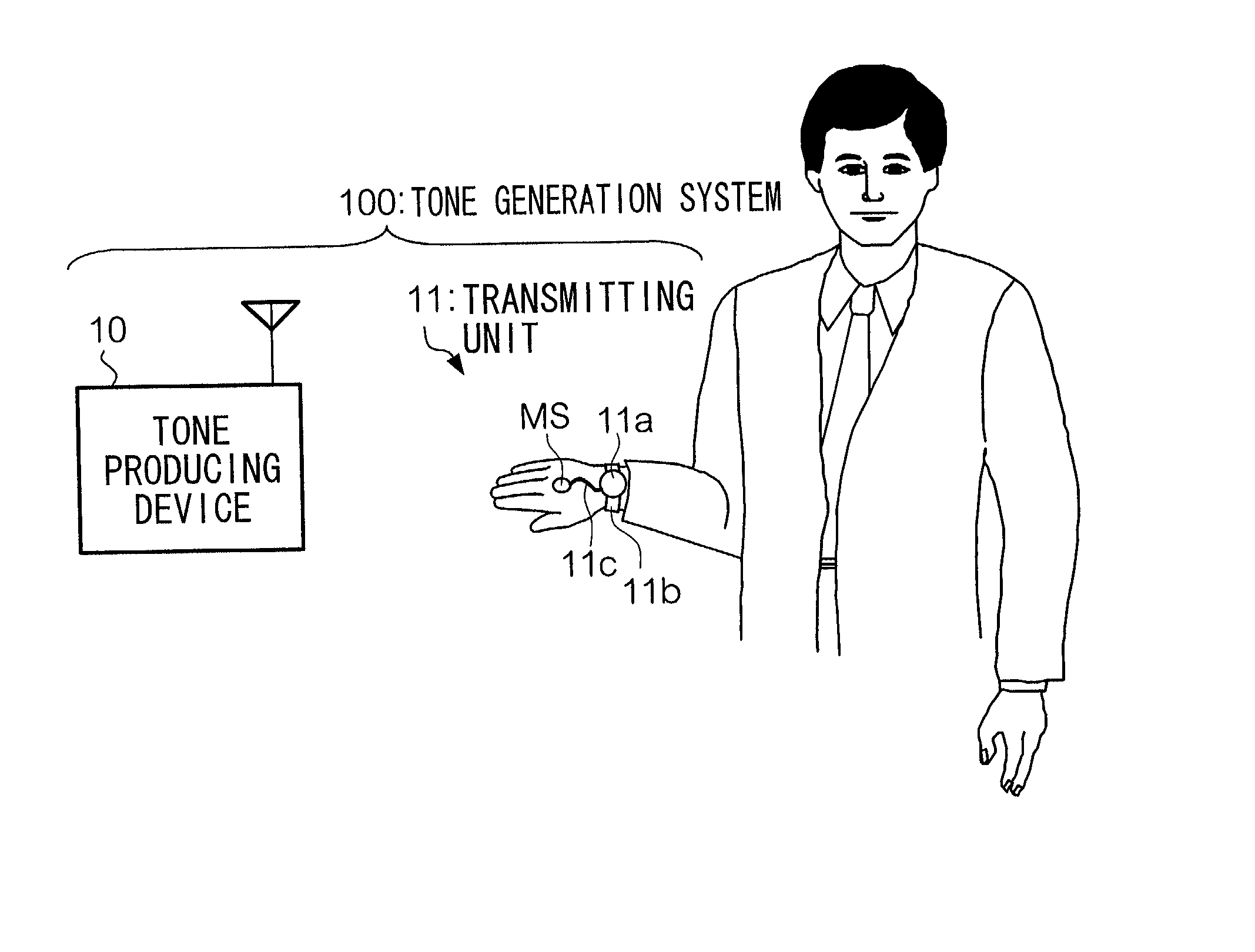
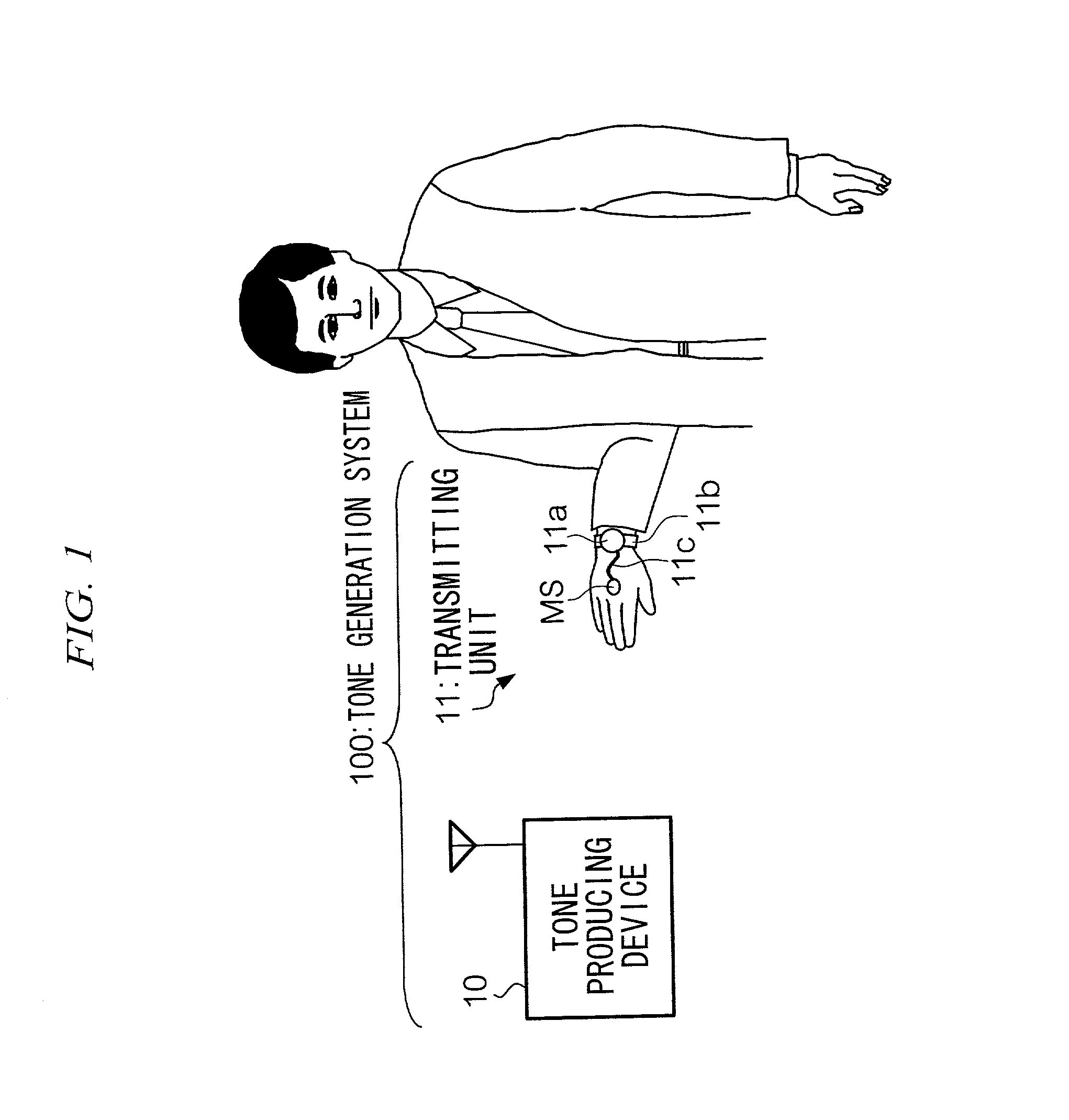
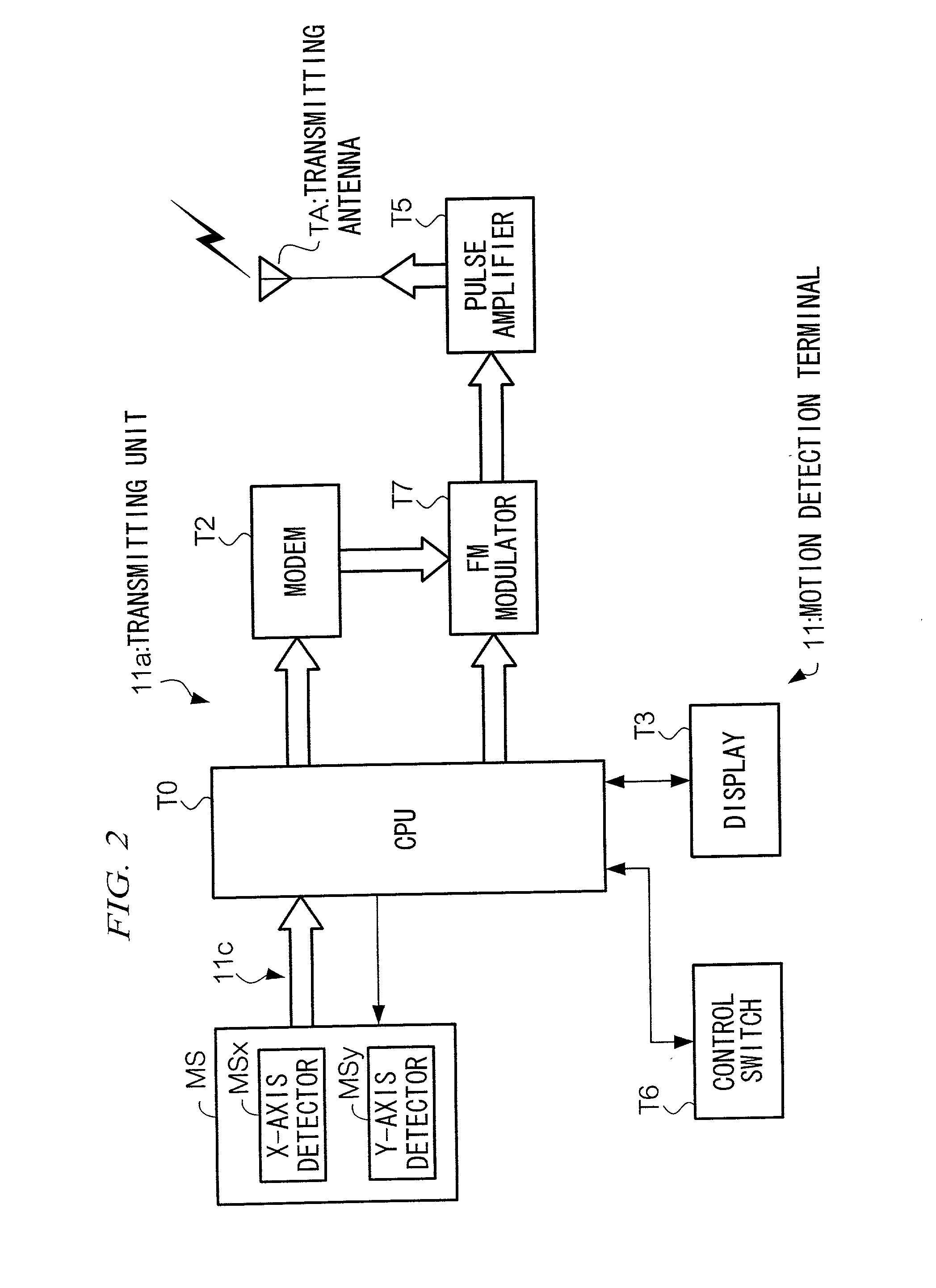
[0023] FIG. 1 is an external perspective view of a tone generation system. As shown, a tone generation system 100 has a tone producing device 10; and a motion detection terminal 11 to be attached to a user's hand. The Motion detection terminal 11 is composed of a sensor unit MS attached to the back of a user's hand; and a transmitting unit 1 la for transmitting to the Tone producing device 10, by radio, motion information detected by the sensor unit MS. Since The Transmitting unit 11a is not attached to a hand, a device to be attached to the back of a hand can be kept both compact and light, thereby enabling a user to execute hand movements with both agility and flexibility. In one example, the Transmitting unit 11a is attached to a user's wrist by means of a band 11b shown in FIG. 1. The Motion sensor MS is connected to the Transmitting unit 11a via a signal line 11c. A signal representing a hand motion detected by the Motion sensor MS is suppli...

modification 1

[0052] In the first embodiment the Motion sensor MS is attached to the back of a hand, to thereby detect torsional motion. As shown in FIG. 7, a rod-like motion detection terminal may be introduced, functioning as both the motion sensor MS and the Transmitting unit 11a. Specifically, a Motion detection terminal 211 shown in FIG. 7 has a cylindrical shape. The Motion detection terminal 211 is used in a predetermined manner that a user holds at both edges, as shown in FIG. 8.

[0053] As shown in FIG. 7, distortion gauges 212a and 212b are attached on the surface of the Motion detection terminal 211, to detect twisting of hands. Each gauge detects an amount of distortion of the surface of the Motion detection terminal 211 in an X-axis direction and a Y-axis direction respectively, which directions are orthogonal to each other. The Transmitting unit 11a is integrated in the Motion detection terminal 211, and information on distortion in X-axis and Y-axis directions, each detected by the D...

modification 2

[0055] In the first embodiment, a hand motion determines a pitch and timbre to be generated. However, it is also possible for a hand motion to govern a tempo, volume, and other parameters. In other words, tone attributes of a music composition can be controlled, such as tempo, volume, effect, and any other attribute parameters that are predetermined prior to reproduction.

[0056] Specifically, the Hard disk drive 33 stores MIDI data. Parameter determination table stores values of tempos instead of pitch or timbre; and corresponding values .theta.x and .theta.y, respectively. Tone producing device plays a piece of music represented by MIDI data. During the playback of the MIDI data, when a hand is in a horizontal position as shown in FIG. 6A the music is played at its normal tempo. When a user bends his or her wrist as shown in FIG. 6B, the music is played, for example, at a faster tempo. Needless to say, other parameters concerning volume and dynamics and adding effects can likewise b...


PUM


Abstract

A tone generating system 100 has a motion detection terminal 11 and a tone producing device. The Motion detection terminal 11 has a motion sensor MS which is attached to the back of a hand, and transmitting unit 11a. The Motion sensor MS detects a torsional motion of the hand to which it is attached. The Transmitting unit 11a transmits motion information on the torsional motion. A Tone producing device 10 receives the motion information, generates control information based on the motion information, and produces a tone on the basis of the control information.

Description

FIELD OF THE INVENTION[0001] The present invention relates to a system for controlling tones to be generated in response to human body movements.DESCRIPTION OF THE RELATED ART[0002] A system is known wherein sensors attached to a human body detect a motion of that part of the body to which they are attached, and on the basis of a characteristic of a movement of that body part, a particular tone is generated. In this related system, each of various body movements is assigned different parameters, whereby a particular tone is generated by the movement of a particular part of the body. Such parameters may be used to control, for example, pitch, timbre, volume, effect, and so on. By using such a system, a user is able to use his / her body as a virtual instrument. Movement of an arm or leg, for example, or a variety of combinations of various movements of some parts of the body results in the generation of different musical tones, or different modifications of attributes of musical tones....

Claims


Application Information

Patent Timeline
IPC IPC(8): A63B24/00A63B69/00A63F13/212A63F13/235A63F13/54A63F13/814G10H1/00G10H1/053
CPCG10H1/0083G10H2220/401G10H2240/056
Inventor NISHITANI, YOSHIKIUSA, SATOSHIKOBAYASHI, EIKOMIKI, AKIRA
Owner YAMAHA CORP
Learn More