Micro cell architecture for mobile user tracking communication system

a communication system and micro cell technology, applied in the field of communication systems, can solve the problems of high system capacity for a limited spectrum, direct conflict between requirements and objectives, and limited transmit power and antenna aperture, and achieve the effect of facilitating user movement detection

Inactive Publication Date: 2002-09-12
DIRECTV LLC
View PDF99 Cites 50 Cited by
  • Summary
  • Abstract
  • Description
  • Claims
  • Application Information

AI Technical Summary

Benefits of technology

[0014] In the illustrative embodiment, the system is implemented in a stratospheric platform based communication system including a hub adapted to communicate with a stratospheric platform. A transceiver and a phased array antenna are disposed on the platform to communicate with the hub and with the user. A second antenna is provided on the platform to communicate with the hub. Beamforming and direction are implemented on the hub and communicated to the platform. The user's position is detected with a global positioning system receiver, by measuring the strength of a signal received from the user, or by other suitable means. On detection of user movement from the first microcell, the beamforming system redirects the beam to follow the user into a second microcell. Additional beams around the user's microcell are illuminated to facilitate detection of the users movement.

Problems solved by technology

For a lightweight platform payload, both the transmit power and the antenna aperture can be limited.
These requirements are in direct conflict with the objective of a lightweight payload.
This would result in higher system capacity for a limited spectrum.

Method used


Image

  • Micro cell architecture for mobile user tracking communication system
  • Micro cell architecture for mobile user tracking communication system
  • Micro cell architecture for mobile user tracking communication system

Examples


Embodiment Construction

[0035] Illustrative embodiments and exemplary applications will now be described with reference to the accompanying drawings to disclose the advantageous teachings of the present invention.

[0036] While the present invention is described herein with reference to illustrative embodiments for particular applications, it should be understood that the invention is not limited thereto. Those having ordinary skill in the art and access to the teachings provided herein will recognize additional modifications, applications, and embodiments within the scope thereof and additional fields in which the present invention would be of significant utility.

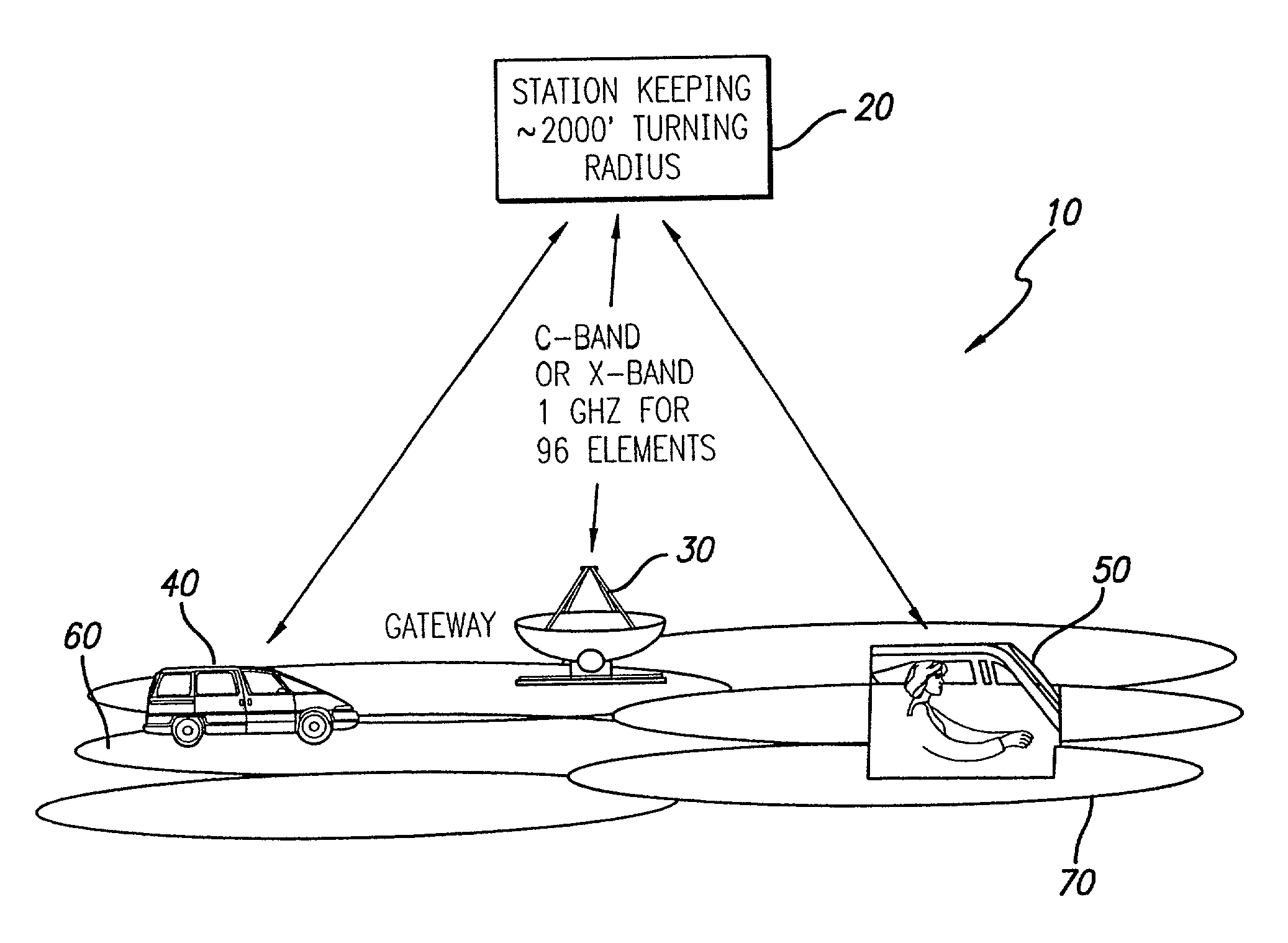
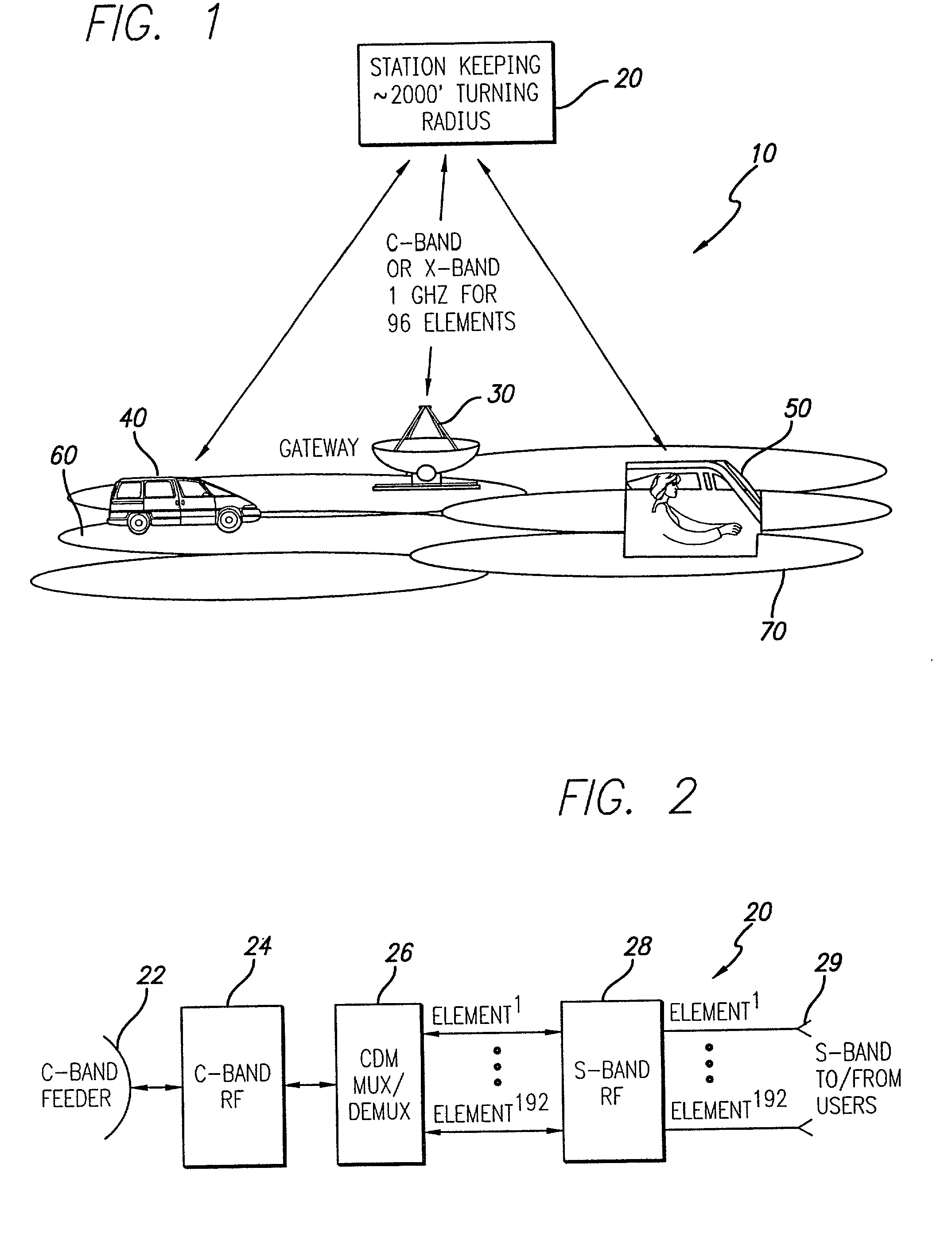
[0037] FIG. 1 is a diagram illustrative of the stratospheric communication system of the present invention with a single stratospheric platform. The inventive system 10 includes a transceiver system 20 mounted on an airborne platform (not shown). In practice, the platform could be an airplane flying in an orbit at 20-30 kilometers (km) above the gr...


PUM


Abstract

A system and method for tracking a user. The system is adapted for use in a wireless communication system and creates a plurality of beams within a coverage area. A first beam is directed at a user in a first microcell and a number of additional beams illuminate microcells immediately adjacent the first microcell. The system is equipped with a mechanism for detecting movement of the user from the first microcell to one of the immediately adjacent microcells. On the detection of movement of the user, the system redirects the first beam from the first microcell to a second microcell, the second microcell being one of the adjacent microcells. In the illustrative embodiment, the system is implemented in a stratospheric platform based communication system including a hub adapted to communicate with a stratospheric platform. A transceiver and a phased array antenna are disposed on the platform to communicate with the hub and with the user. A second antenna is provided on the platform to communicate with the hub. Beamforming and direction are implemented on the hub and communicated to the platform. The user's position is detected with a global positioning system receiver, by measuring the strength of a signal received from the user, or by other suitable means. On detection of user movement from the first microcell, the beamforming system redirects the beam to follow the user into a second microcell. Additional beams around the user's microcell are illuminated to facilitate detection of the users movement.

Description

[0001] This application is a continuation of now pending application bearing Ser. No. 09 / 587,758, filed Jun. 6, 2000, for "MCIRO CELL ARCHITECTURE FOR MOBILE USER TRACKING COMMUNICATION SYSTEM", inventors: Donald C. D. Chang et. al, the entire contents of which are incorporated herein by this reference.BACKGROUND OF THE INVENTION[0002] 1. Field of the Invention[0003] The present invention relates to communications systems. More specifically, the present invention relates to architectures for data / voice services to mobile users using stratospheric platforms.[0004] 2. Description of the Related Art[0005] Stratospheric platforms are being considered for data / voice communication applications. Current proposals envision a mounting of transceivers and antennas on aircraft flying at 20-30 kilometers above the earth which will project beams to cell sites located on the ground.[0006] Copending U.S. patent application Ser. No. 09 / 588,395, filed Jun. 6, 2000 by D. Chang et al., entitled STRATO...

Claims


Application Information

Patent Timeline
Patent Type & Authority Applications(United States)
IPC IPC(8): H04B7/06H04B7/08H04B7/185
CPCH04B7/0617H04B7/086H04B7/18504
Inventor CHANG, DONALD C.D.FERIA, YINGWANG, WEIZHENGCHA, ALANCHANG, MINGHAGEN, FRANK A.YUNG, KAR W.
Owner DIRECTV LLC
Why Eureka
Try Eureka