
Receiving apparatus, receiving method, program and information recording medium

a technology for receiving apparatuses and information recording mediums, applied in the direction of orthogonal multiplexes, amplitude demodulation, baseband system details, etc., can solve the problems of amplitude phase variation in reception signals, schemes may have a difficulty in adequately predicting transmission characteristics

Active Publication Date: 2002-09-12
NAT INST OF INFORMATION & COMM TECH +1
View PDF7 Cites 20 Cited by
  • Summary
  • Abstract
  • Description
  • Claims
  • Application Information

AI Technical Summary

Benefits of technology

0115] The prediction section in the receiving apparatus of the invention or the prediction step in the receiving method of the invention can be designed in such a way as to let H.sup.-1(f, n-1) be H.sup.-1(f, n) in place of the average value over the range of the time series of amplitude phase ratios when the exclusion condition is satisfied for an integer n.

Problems solved by technology

Direct adaptation of the conventional OFDM packet communication to a mobile environment however cause an amplitude phase variation in a reception signal due to multipath fading.
It is however known that those schemes may have a difficulty in adequately predicting the transmission characteristic when the Doppler frequency is high at a specific sub-carrier which has been affected by the frequency selectivity fading and the signal amplitude phase varies significantly.

Method used


Image

  • Receiving apparatus, receiving method, program and information recording medium
  • Receiving apparatus, receiving method, program and information recording medium
  • Receiving apparatus, receiving method, program and information recording medium

Examples


embodiment

[0133] (Embodiment)

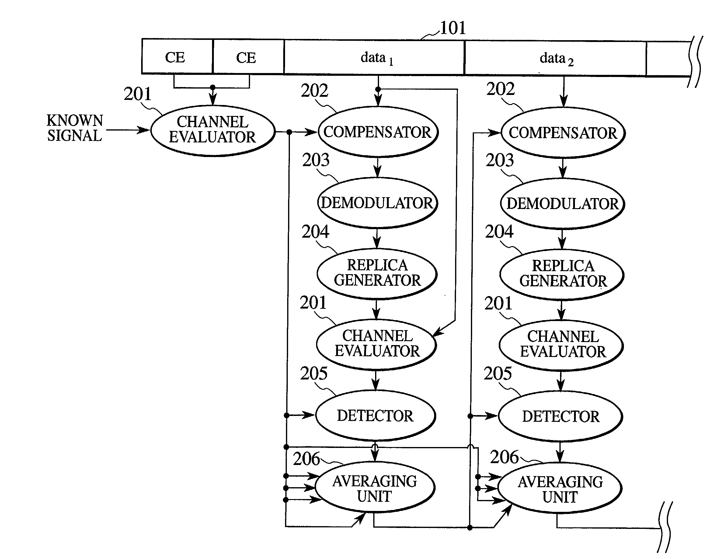
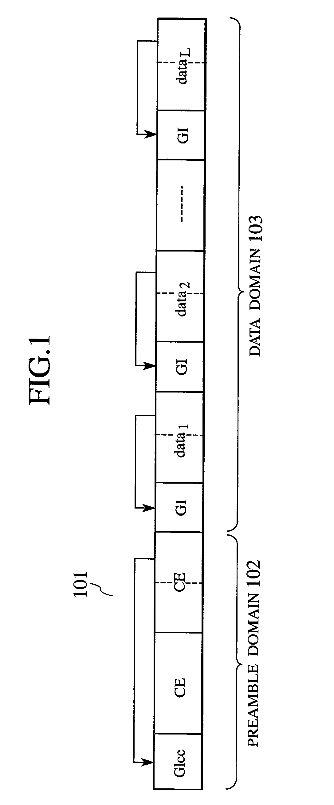
[0134] FIG. 1 shows the frame format of an OFDM packet which is used in one embodiment of the invention. The format will be discussed below referring to this diagram.

[0135] A frame (burst) 101 comprises a preamble domain 102 and a data domain 103.

[0136] The preamble domain 102 includes two known symbols CE and a single guard interval GIce.

[0137] The number of the known symbols CE may be set greater. In case where there are a plurality of known symbols CE, the transmission path is predicted by using the average of those reception symbols.

[0138] The data domain 103 includes plural pieces of data to be transmitted (data.sub.1, . . . , data.sub.L) and L guard intervals GI for separating those data.

[0139] As transmission is possible by using a plurality of modulation systems and coding rates according to the IEEE 802.11a standards, coding is carried out at the coding rate of 1 / 2 and an OFDM symbol "SIGNAL" modulated with BPSK (Binary Phase-Shift Keying) is placed after...


PUM


Abstract

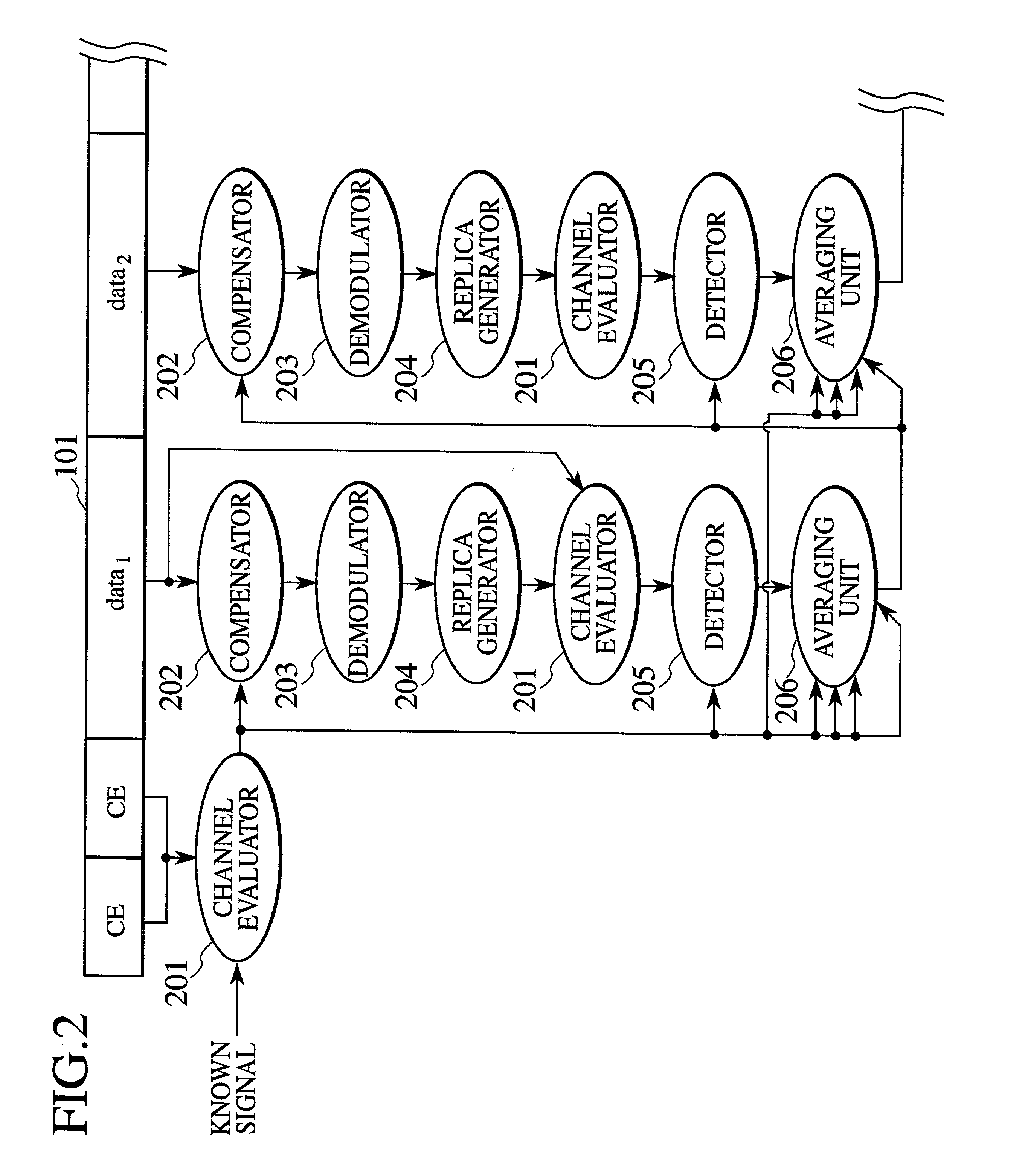
A channel evaluator acquires a change predicted value from a known symbol, and a compensator compensates for a first symbol using the change predicted value. A demodulator restores a portion corresponding to this symbol with another subcarrier. A replica generator acquires a transmission replica of the restored symbol. The channel evaluator performs complex division on the replica with the symbol to acquire an amplitude phase ratio. A detector compares the amplitude phase ratio with an amplitude phase ratio acquired immediately previously. In case where an elimination condition is satisfied, the detector disregards the amplitude phase ratio acquired currently and uses an immediately previous value instead, an averaging unit averages amplitude phase ratios to acquire a next change predicted value, and the compensator compensates for a next symbol using the change predicted value. Hereinafter, the sequence of processes is repeated.

Description

BACKGROUND OF THE INVENTION[0001] 1. Field of the Invention[0002] The present invention relates to a receiving apparatus and a receiving method which are suitable for adaptively predicting the transmission characteristic in case where OFDM (Orthogonal Frequency Division Multiplex) packet communication is executed under a fast mobile environment, a program which achieves the receiving apparatus and method, and a computer readable information recording medium which has the program recorded thereon.[0003] 2. Description of the Related Art[0004] Recently, the quick spreading of the Internet or the like is contributing to the construction of environments under which a vast amount of information, such as multimedia information, can exchanged anytime and anywhere. Demands for mobile computing to ensure transmission of such a vast amount of information under a mobile environment using portable telephones and PHS (Personal Handyphone Systems) as well as via cable networks.[0005] In this resp...

Claims


Application Information

Patent Timeline
Patent Type & Authority Applications(United States)
IPC IPC(8): H04B1/10H04L25/02H04J11/00H04L25/03H04L27/26
CPCH04L25/0204H04L25/022H04L25/0224H04L27/2647H04L2025/03414
Inventor HARADA, HIROSHIFUJISE, MASAYUKIFUNADA, RYUUHEISAWADA, MANABUSASAKI, KUNIHIKO
Owner NAT INST OF INFORMATION & COMM TECH
Learn More