Dynamic brake with backlash control for peristaltic pump

a technology of peristaltic pump and backlash control, which is applied in the direction of positive displacement liquid engine, prosthesis, instruments, etc., can solve the problems of air entering the conduit, air embolism or even death of patients, and the roller pump to experience some recoil, so as to prevent backlash

Inactive Publication Date: 2002-09-12
TERUMO CARDIOVASCULAR SYST CORP
View PDF0 Cites 36 Cited by
  • Summary
  • Abstract
  • Description
  • Claims
  • Application Information

AI Technical Summary

Benefits of technology

0011] It is an object of the present invention to provide an intelligen

Problems solved by technology

However, when the rollers are left free to move, it is common for the roller pump to experience some recoil, that is, some amount of counter rotation (e.g., 20 degrees of counter rotation) im

Method used


Image

  • Dynamic brake with backlash control for peristaltic pump
  • Dynamic brake with backlash control for peristaltic pump
  • Dynamic brake with backlash control for peristaltic pump

Examples


Embodiment Construction

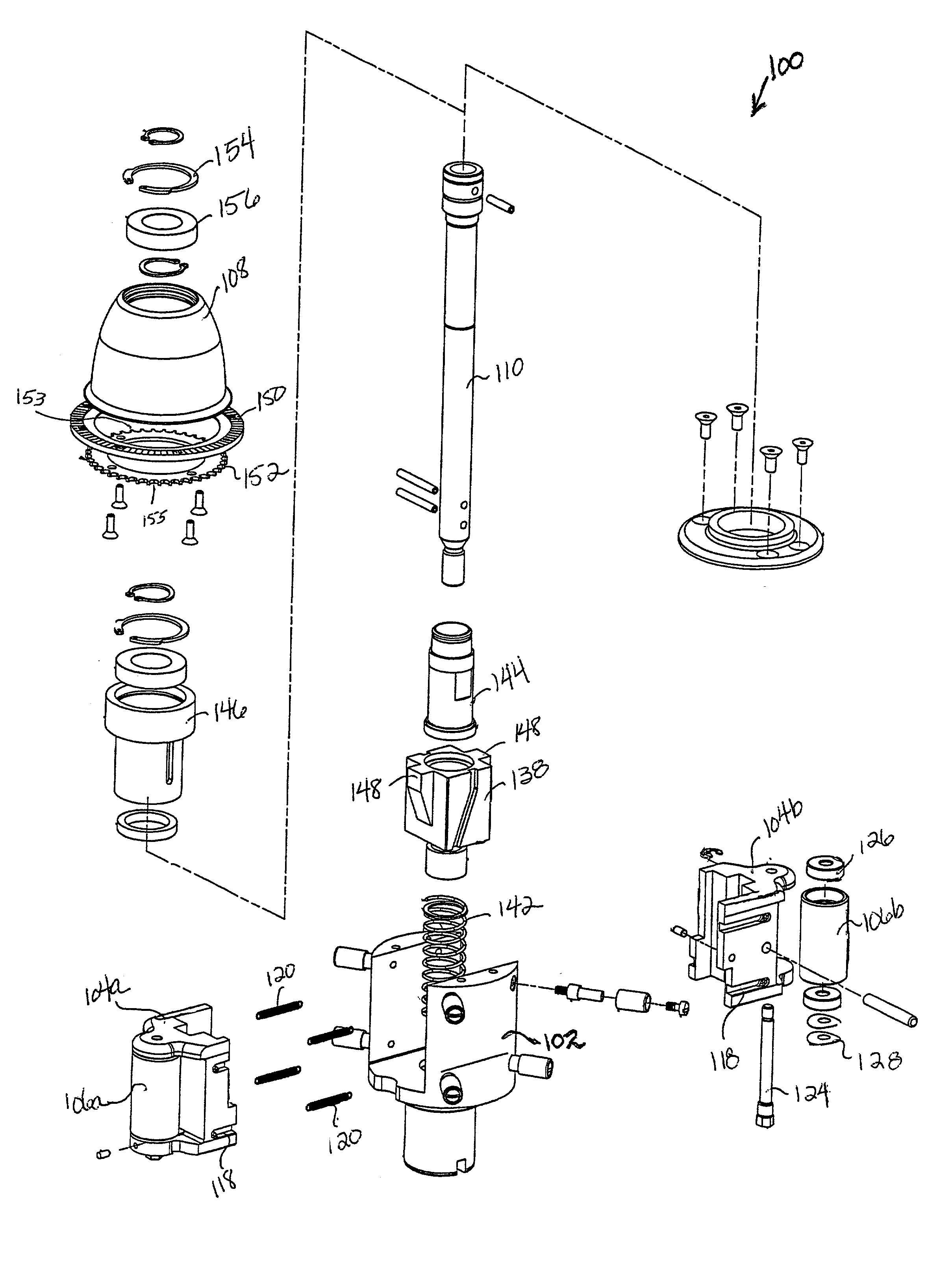
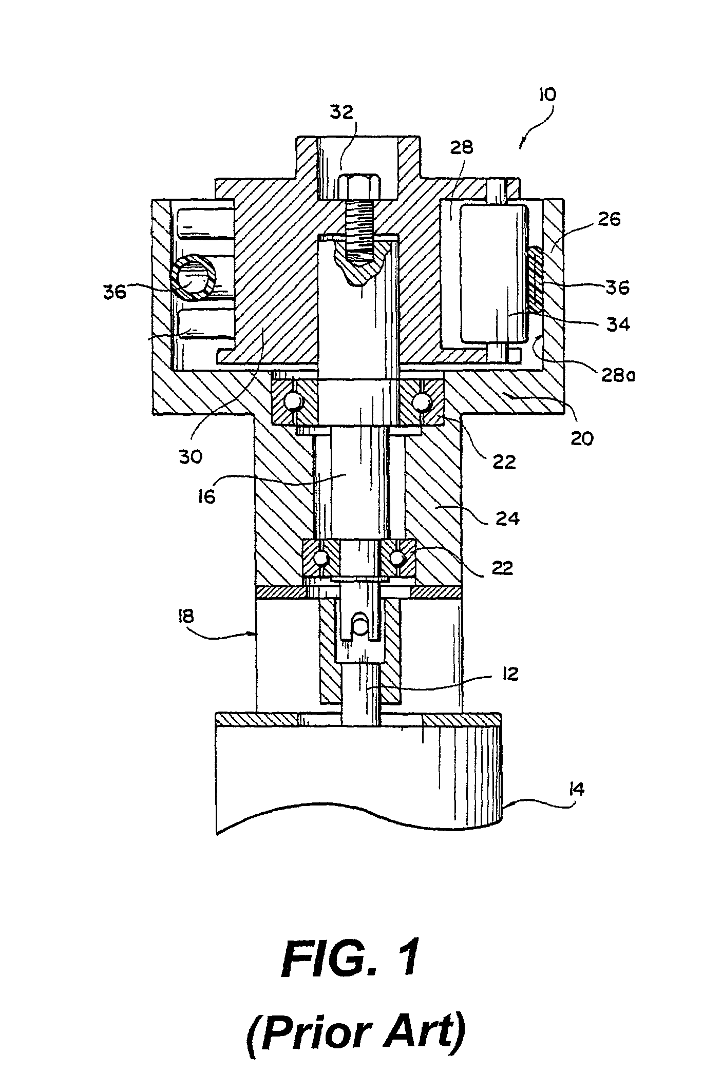
[0021] A peristaltic pump rotor assembly according to the present invention is shown generally by reference numeral 100 in the exploded view of FIG. 3. Rotor assembly 100 includes a pump or rotor hub 102, at least one and preferably two opposing roller slides 104a, 104b, a roller 106a, 106b disposed within each roller slide, respectively, and an adjustment knob 108 for adjusting the occlusion of the flexible tube within the pump housing. The rotor assembly 100 is rotatably supported within a stator similar to that shown in FIG. 1 and as known in the art, and the inner circumferential surface of the stator forms the raceway for the rollers 106a, 106b of the present invention. A main shaft 110 extending through the rotor assembly 100 rotates according to the rotation of a drive shaft, which is rotated by a conventional drive mechanism, as shown in FIG. 1, for example.

[0022] Each of the roller slides 104a, 104b includes a plurality of recesses or channels 118 for receiving an extension...


PUM


Abstract

The present invention involves a dynamic brake for use in a peristaltic (i.e., roller) pump. The dynamic brake avoids backlash, due to counter rotation. In addition, it does not preclude the option of hand operating the roller pump. This is achieved by initiating the braking operation after the roller pump set-point has been set to zero and only after the roller pump has decelerated below a predefined speed (e.g., 20 rpm). In addition, the braking operation is activated for only a very brief period of time (i.e., a period of time required for the pressure in the roller pump fluid conduit to subside).

Description

TECHNICAL FIELD[0001] The present invention is directed to a dynamic brake with backlash control, and more particularly, to a dynamic brake with backlash control for use with a peristaltic pump.BACKGROUND OF THE INVENTION[0002] Peristaltic pumps, also referred to as roller pumps, are commonly utilized in medical applications. For instance, such pumps are often employed during cardiovascular surgery to facilitate circulation of blood between a patient and a heart-lung machine. Other common medical uses are the transfer of blood between a patient and a kidney dialyzer, and intravenous feeding of IV solutions. Generally, peristaltic pumps are simply structured, generate a constant flow, and employ disposable tubes as a member for fluid transfer.[0003] Peristaltic pumps are relatively simple in construction and typically include a housing having rollers which progressively compress a flexible tube at spaced intervals against an arcuate surface or raceway so as to flatten or locally redu...

Claims


Application Information

Patent Timeline
IPC IPC(8): F04B49/06A61M1/00A61M1/10A61M1/32A61M1/36F04B43/00F04B43/12G16H20/17G16H20/40G16Z99/00H02P3/06
CPCA61M2205/3365G06F19/00A61M2205/50A61M2205/502A61M2205/505F04B43/0081F04B43/1253F04B43/1276F04B49/065F04B2205/04F04B2207/70G06F19/3481A61M1/00A61M1/10A61M1/101A61M1/32A61M1/3621A61M1/3666A61M1/367G16H40/63A61M1/34A61M2205/103A61M1/3403A61M1/1039A61M1/1046A61M1/1086A61M2205/3334A61M2205/35G16H20/17G16H20/40A61M60/279G16Z99/00A61M60/113A61M60/508A61M60/441
Inventor LUCKE, LORI E.DANIELSON, DAVIDGRIEWSKI, RICHARD A.
Owner TERUMO CARDIOVASCULAR SYST CORP
Why Eureka
Try Eureka