Mechanical and acoustical suspension coating of medical implants

a suspension coating and medical implants technology, applied in the field of coating medical implants, can solve the problems of difficult to achieve uniform thickness of coating, spot holding of parts, and requiring subsequent coating steps

Inactive Publication Date: 2002-09-12
SCI MED LIFE SYST
View PDF1 Cites 53 Cited by
  • Summary
  • Abstract
  • Description
  • Claims
  • Application Information

AI Technical Summary

Problems solved by technology

Although these processes have been used to produce satisfactory coatings, there are numerous potential drawbacks associated therewith.
For example, it is often difficult to achieve coatings of uniform thickness, both on individual parts and on batches of parts.
Also, many of these conventional coating processes require that the coated part be held during coating, resulting in defects such as bare spots where the part was held and thus requiring subsequent coating steps.

Method used


Image

  • Mechanical and acoustical suspension coating of medical implants
  • Mechanical and acoustical suspension coating of medical implants
  • Mechanical and acoustical suspension coating of medical implants

Examples


first embodiment

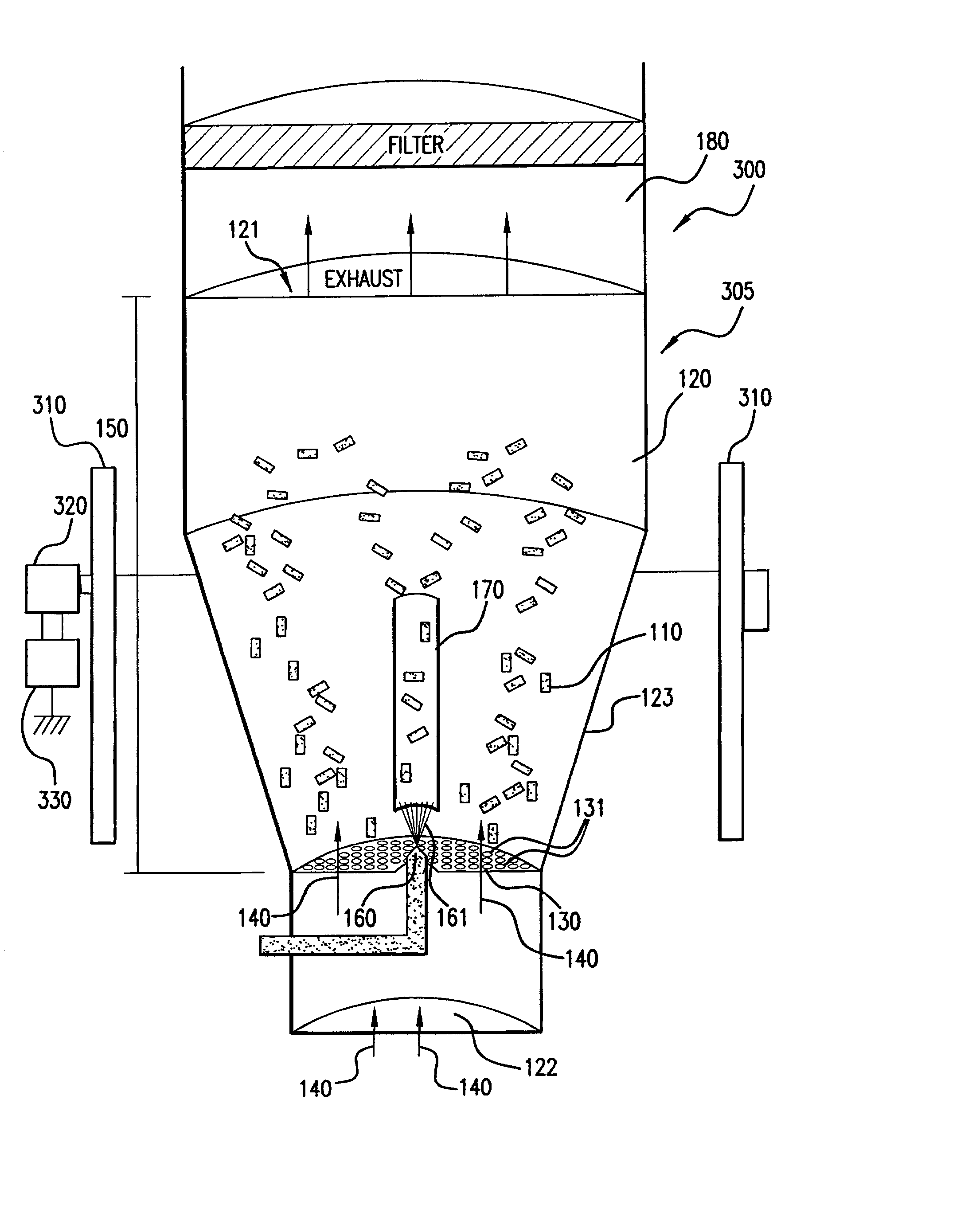
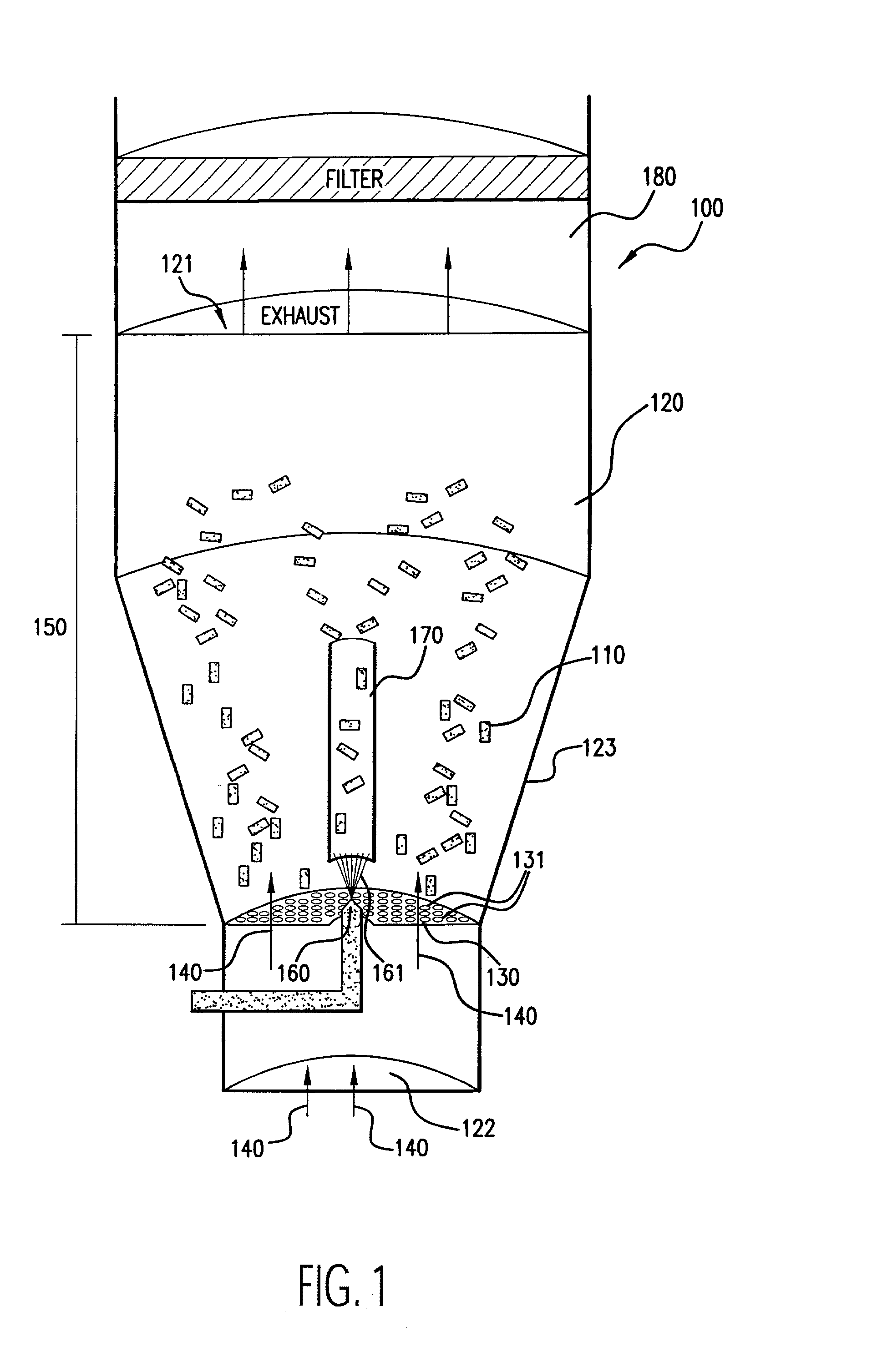
[0033] As stated above, the first embodiment for an apparatus for coating medical devices 100 in accordance with the principles of the present invention is illustrated in FIG. 1. In FIG. 1, medical devices 110 are placed in a chamber 120. The chamber 120 includes a top opening 121 for exhaust, a bottom opening 122 for introduction of input air 140, and at least one side wall 123. Although the chamber 120 is shown to generally include a structure having a tapered, cylindrical shape, the chamber 120 may be of any suitable shape, such as rectangular. The tapered configuration of the chamber 120 as shown in FIG. 1 is generally preferred to facilitate a cyclical air flow within the chamber 120. The coating process of the present invention occurs within the chamber 120.

embodiment 100

[0034] The embodiment 100 includes an air distribution plate 130, which is secured to the side wall 123 of the chamber 120. The air distribution plate 130 has openings 131 that are smaller than the smallest dimension of the medical devices 110 so that the medical devices 110 cannot fall through it. The purpose of the air distribution plate 130 is to channel input air 140, introduced into the chamber 120 from its bottom opening 122, into the coating region 150 of the chamber 120 to assist in the fluidization and coating of the medical devices 110. The air distribution plate 130 is of any suitable shape to achieve this purpose, such as planar (as shown in FIG. 1) or concave configurations.

[0035] The air distribution plate 130 is of any suitable structure that permits the flow of air therethrough such as, for example, a perforated metal or ceramic plate or screen. Preferably, the air distribution plate 130 has an open area (i.e., the planar surface area of openings) of about 4 to about...

example 1

[0110] Coronary stents are coated with a polymeric coating solution in accordance with the present invention.

[0111] Numerous (approximately 300 to 600 in this example) NIR stents (Medinol, Tel Aviv) are placed in a Wurster fluidized bed chamber, such as a GPCG-1 (available from Glatt Air Techniques, Ramesey, N.J.). The stents are each about 9 mm-32 mm in length, about 1.5 mm-3.0 mm in diameter, about 7 mg-35 mg in weight, and about 46-200 mm.sup.2 in surface area.

[0112] A coating solution of polyurethane is prepared by mixing the following components (in approximate weight percentages): 0.5-1.0% Corethane 50D (Corvita, Miami, Fla.), 1.0-10.0% dimethylacetamide, and balance tetrahydrofuran. The solution components are mixed using a magnetic stirrer for at least about 8 hours to form a solution or dispersion, which is thereafter filtered with a 1.0 micron Teflon filter.

[0113] The stents are suspended using fluidizing air at about 2-20 psi, at a temperature of about 20-90 C. and a dew ...


PUM

PropertyMeasurementUnit
thicknessaaaaaaaaaa
thicknessaaaaaaaaaa
operating temperaturesaaaaaaaaaa

Abstract

The present invention has several plausible embodiments. In one embodiment an apparatus for coating a medical device is provided. This apparatus includes a coating chamber, a vibrating structure within the coating chamber the vibrating structure capable of suspending a medical device positioned in the coating chamber, and a coating source, the coating source positioned to introduce coating into the coating chamber. In another embodiment a method of coating a medical device is provided. This method includes moving a medical device into a predetermined coating area, vibrating a structure below the medical device, the vibration of the structure forcing the medical device away from the vibrating structure, and coating at least a portion of the medical device that has moved away from the vibrating structure.

Description

[0001] This application is a continuation-in-part of pending application Ser. No. 09 / 804,040, filed Mar. 13, 2001, which is a continuation-in-part of pending application Ser. No. 09 / 551,614, filed Apr. 17, 2000, now U.S. Pat. No. _______, which is a continuation-in-part of application Ser. No. 09 / 293,994, filed Apr. 19, 1999, now abandoned.FIELD OF THE INVENTION[0002] The present invention relates to coating medical implants. More specifically, the present invention regards coating medical implants that are agitated or moved due to the vibration of a vibrating structure.BACKGROUND OF THE INVENTION[0003] It is often beneficial to coat medical devices so that the surfaces of such devices have desired properties or effects. For example, it is useful to coat medical devices to provide for the localized delivery of therapeutic agents to target locations within the body, such as to treat localized disease (e.g., heart disease) or occluded body lumens. Such localized drug delivery avoids t...

Claims


Application Information

Patent Timeline
Patent Type & Authority Applications(United States)
IPC IPC(8): A61L27/28A61L27/34A61L27/54A61L29/08A61L29/16A61L31/08A61L31/10A61L31/16B05B13/02B05C13/00B05D1/22
CPCA61L27/34A61L27/54A61L29/085A61L29/16A61L31/10A61L31/16A61L2300/606B05B13/02B05B13/0221B05B13/025B05B13/0257B05C13/00B05D1/22Y10S118/05
Inventor SCHWARZ, MARLENE C.TOCKER, STANLEY
Owner SCI MED LIFE SYST
Why Eureka
Try Eureka