Watercraft with steer-responsive throttle

a technology of responsive throttle and watercraft, which is applied in the field of steering system, can solve the problems unsuitable rudder for many jet boats, personal watercraft, jet skis and motorboats, etc., and achieves the effect of limiting the rpm of the motor

Inactive Publication Date: 2002-09-12
MICHEL CAMILLE +1
View PDF0 Cites 8 Cited by
  • Summary
  • Abstract
  • Description
  • Claims
  • Application Information

AI Technical Summary

Benefits of technology

0004] U.S. Pat. No. 3,183,379 (Heidner) discloses a speed control device for use primarily on an outboard motor. When a motorboat that is either at rest or traveling at low speed is steered sharply (i.e. beyond a predetermined angle), a limiting rod interferes with the rotation of a throttle control member thereby limiting the RPM of the motor. The throttle control has a cam with a lobe that catches the limiting rod when the limiting rod is pressed against the cam. This prevents the boat from capsizing when the throttle is suddenly advanced and the motor is already set for a sharp turn. Since the danger of capsizing is significantly less when the boat is already traveling above a predetermined speed, the speed control device allows the motor to be swiveled through a full extent without actuating the limiting rod and interfering with the throttle control member. The predetermined speed (or RPM) above which the throttle control member becomes unconstrained by the limiting rod corresponds to an angular position of the cam at which the leading edge of the lobe has been rotated at least slightly beyond the line of action of the limiting rod.

Problems solved by technology

When a motorboat that is either at rest or traveling at low speed is steered sharply (i.e. beyond a predetermined angle), a limiting rod interferes with the rotation of a throttle control member thereby limiting the RPM of the motor.
However, such a rudder is unsuitable for many jet boats, personal watercraft, jet skis and motorboats because they preclude these watercraft from operating in shallow waters which is where these watercraft are commonly used.

Method used


Image

  • Watercraft with steer-responsive throttle
  • Watercraft with steer-responsive throttle
  • Watercraft with steer-responsive throttle

Examples


Embodiment Construction

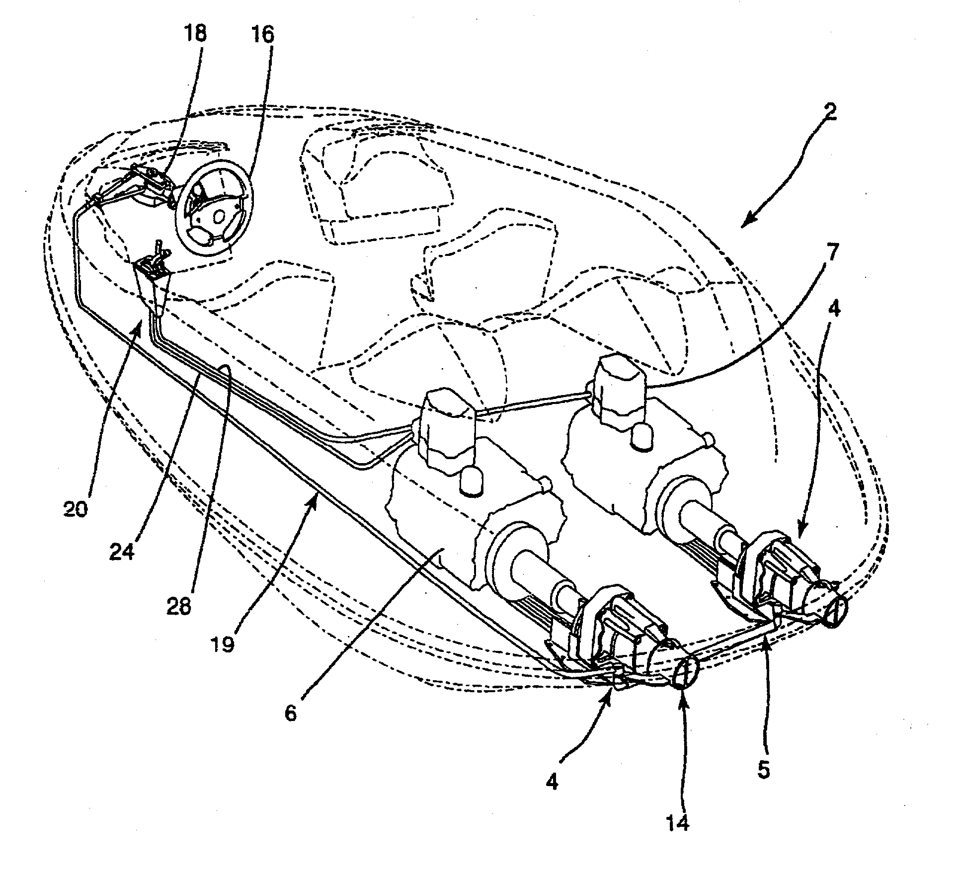
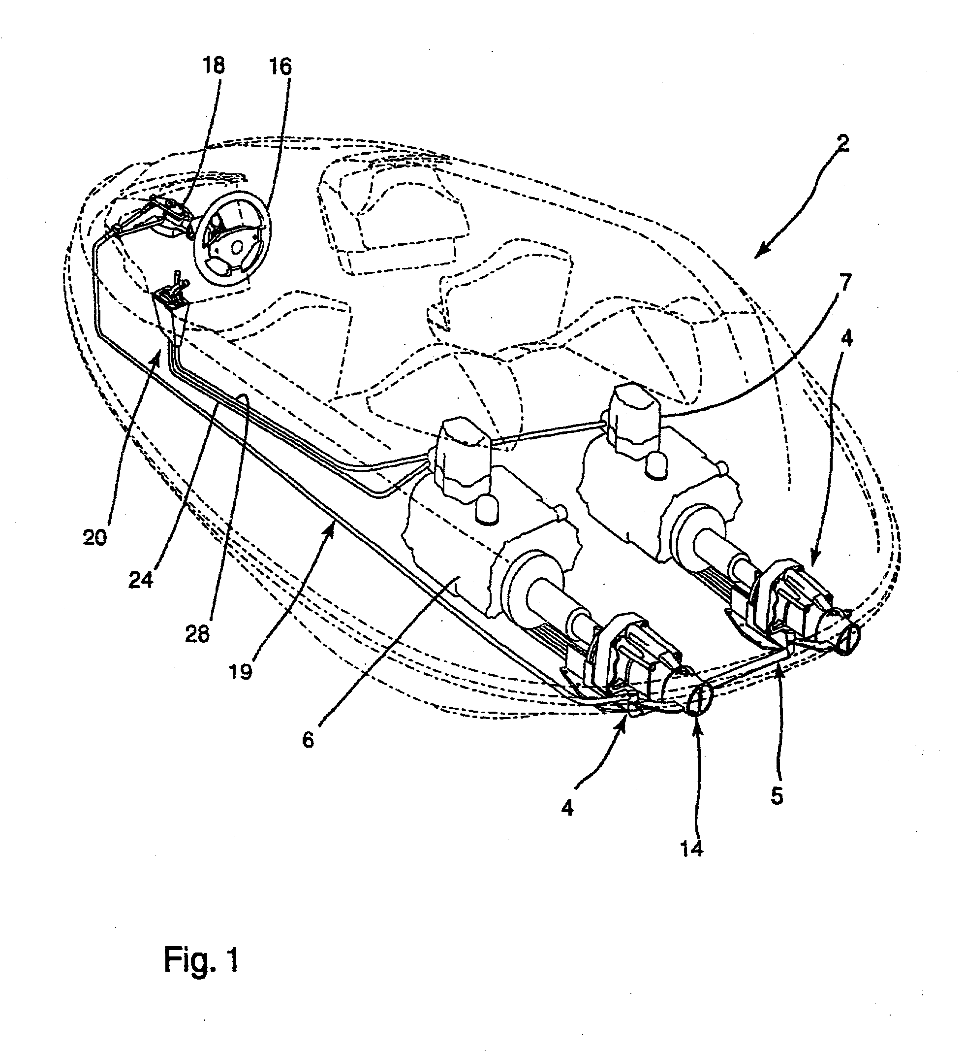
[0064] FIG. 1 illustrates in stippled lines a watercraft generally designated by the reference numeral 2. The watercraft 2 has a pair of steerable propulsion units 4. It should be noted that the watercraft could be a jet boat, a personal watercraft, a jet ski or a motorboat equipped with a swivel-mounted outboard motor. In fact, the present invention is applicable to any watercraft whose propulsion unit can be turned for steering the watercraft. The watercraft can have a single steerable propulsion unit, twin steerable propulsion units (as shown in FIG. 1) or a plurality of steerable propulsion units. When the watercraft has more than one steerable propulsion unit, there is usually a coupling link 5 that rigidly couples the steerable propulsion units together. In the case of a motorboat, there can be a single outboard motor or a plurality of outboard motors (which are usually coupled by a coupling link).

[0065] As shown in FIG. 1, by way of example only, the steerable propulsion unit...


PUM


Abstract

A watercraft with a steer-responsive throttle generates thrust when the steerable propulsion unit is turned beyond a predetermined angular threshold. The turning of the steering wheel beyond the threshold causes the throttle to be opened so that the steerable propulsion unit produces a thrust at least equal to the minimal propulsive force needed to effectively steer the watercraft. A watercraft equipped with a steerresponsive throttle ensures that there is always sufficient thrust for steering the watercraft even when the operator fails to open the throttle manually. This steerresponsive throttle is applicable to single-engine personal watercraft, twin-engine jet boats or motorboats equipped with swivel-mounted outboard motors. In a first embodiment of the steer-responsive throttle, rotation of the steering wheel beyond the angular threshold causes an actuating cable to open the throttle. In a second embodiment, an electronic control system regulates the throttle by calculating the optimal throttle setting based on measurements derived from a speed sensor, a steering angle sensor and, optionally, a throttle position sensor.

Description

[0001] The present application claims priority to and is a continuation of U.S. application Ser. No. 09 / 961,387, filed Sep. 25, 2001, which is a continuation of U.S. application Ser. No. 09 / 383,073, filed Aug. 26, 1999, and issued as U.S. Pat. No. 6,336,833, which is a continuation-in-part of U.S. application Ser. No. 08 / 782,490, filed Jan. 10, 1997, now abandoned. This application relates to co-pending U.S. application Ser. No. 09 / 904,742, which is also a continuation of U.S. application Ser. No. 08 / 782,490. The entirety of each of the above identified applications are hereby incorporated into the present application by reference.FIELD OF THE INVENTION[0002] The present invention relates to watercraft with steerable propulsion units and, more particularly, to a steering system for such a watercraft.BACKGROUND OF THE INVENTION[0003] A watercraft equipped with a steerable propulsion unit can only be steered effectively when the propulsion unit is generating thrust. Examples of waterc...

Claims


Application Information

Patent Timeline
Patent Type & Authority Applications(United States)
IPC IPC(8): B63H21/22F02B61/04F02D11/02G05G11/00
CPCB63H21/21B63H21/22F02B61/045F02D11/02G05G11/00
Inventor MICHEL, CAMILLERHEAULT, ALAIN
Owner MICHEL CAMILLE
Why Eureka
Try Eureka