Automatic transmit power control loop

a transmission power and automatic technology, applied in the field of telecommunications devices, can solve the problems of increased distortion output level, degrading system performance, and additional interference in the uplink channel

Inactive Publication Date: 2002-09-12
SIEMENS AG
View PDF9 Cites 56 Cited by
  • Summary
  • Abstract
  • Description
  • Claims
  • Application Information

AI Technical Summary

Benefits of technology

0011] A wireless telephone according to an embodiment of the present invention includes a transmitter having a power coupler, and a controller implementing a level detector and a gain control unit, one or more transmit DACs, and memory. Nominal values for transmit DAC vs. transmit power are stored in the memory, as is a coupler vs. transmit power response. If the set power is above a threshold, then the nominal transmit DAC value associated with the set power is used to set the transmit DAC. The output of the po

Problems solved by technology

This is primarily due to the increased distortion output levels of the power amplifier at high powers.
In the mobile radio standard IS-95, for example, poorly regulated transmit power at the wireless terminal can lead to near-far effect at the base station demodulator, thus degrading the performance of the system.
Similarly, in IS-136, drift i

Method used


Image

  • Automatic transmit power control loop
  • Automatic transmit power control loop
  • Automatic transmit power control loop

Examples


Embodiment Construction

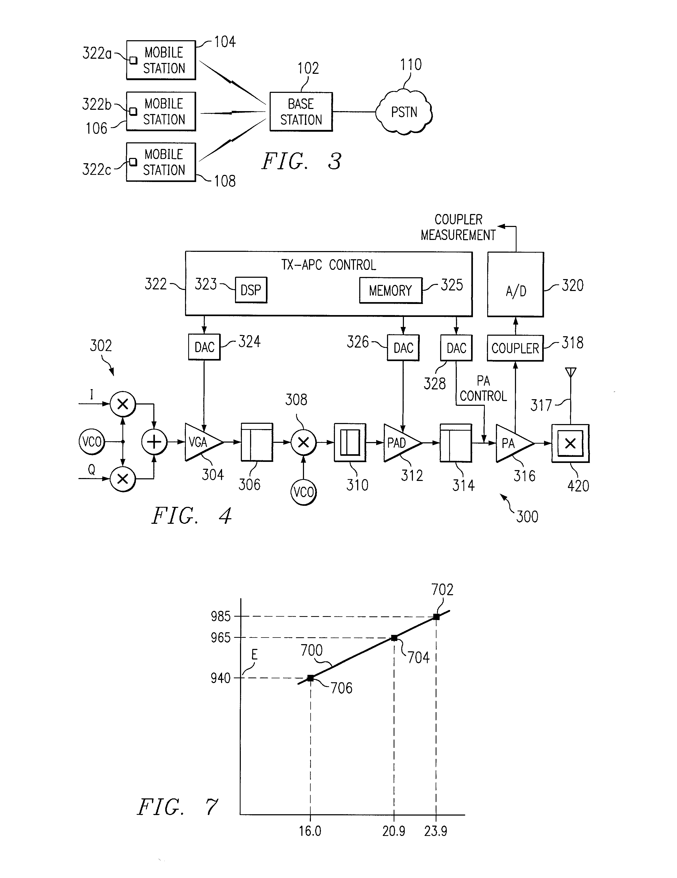
[0022] Turning now to the drawings and, with particular attention to FIG. 3, a diagram of a telecommunications system 100 according to an embodiment of the present invention is shown. The system 100 may be an IS-136 or IS-95 or GSM based telecommunications network, for example. The system 100 includes at least one base station 102 serving a particular geographic region and a plurality of mobile stations 104, 106, 108 which may move in and out of the region. The base station 102 couples the mobile stations to the public switched telephone network (PSTN) 110. In addition, the mobile stations 104, 106, 108 include transmit power control units 322a-322c, respectively, according to embodiments of the present invention

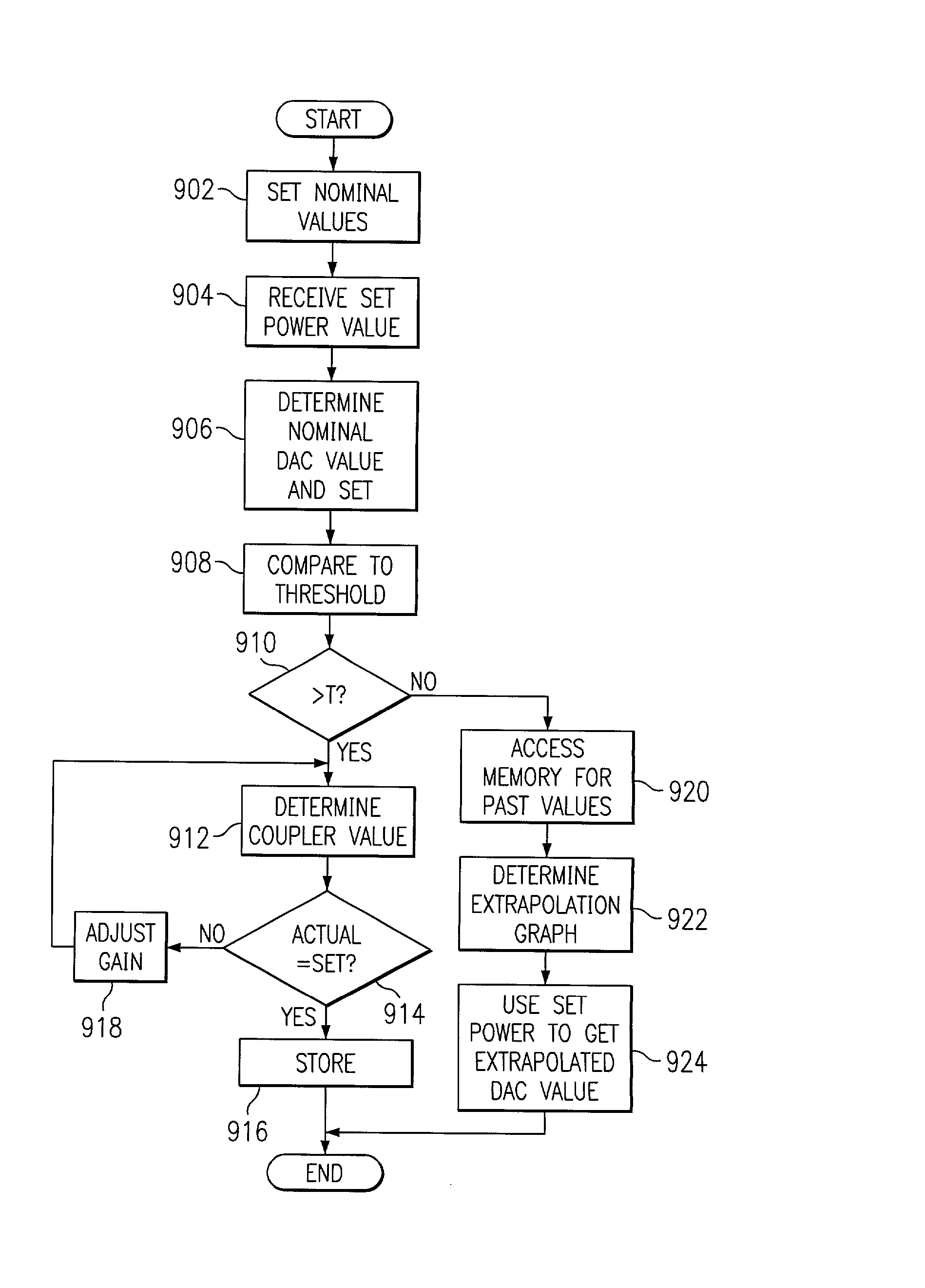
[0023] More particularly, a nominal transmit automatic power control (APC) digital-to-analog converter (DAC) vs. transmit power values and coupler output vs. transmit power values are initialized. Then, a transmit power value is set. If the value is above a threshold, a coup...


PUM


Abstract

A transmitter includes a coupler (318) to measure output power. The output power is compared to a set value and a threshold. If the power is above the threshold, the gain of an output amplifier (316) is adjusted toward the set value. If the power is below the threshold, an extrapolation of the linear portion is used to obtain the set power level.

Description

CROSS REFERENCE TO RELATED APPLICATIONS[0001] The present application claims priority from U.S. Provisional Application Serial No. 60 / 274,554 (Attorney Docket No. 01P4224US), filed Mar. 8, 2001; from U.S. Provisional Application Serial No. 60 / 274,555(Attorney Docket No. 01P4228US) filed Mar. 8, 2001; and from U.S. Non-provisional Application Ser. No. 09 / 952,346 (Attorney Docket No. 01P4228US01) filed Sep. 14, 2001; which are hereby incorporated by reference in entirety as if fully set forth herein.BACKGROUND OF THE INVENTION[0002] The present invention relates to telecommunications devices and, in particular, to an improved automatic power control loop for a wireless telecommunications transmitter.[0003] The Federal Communications Commission (FCC) regulates the use of the radio frequency (RF) spectrum in the United States. Users of allocated bandwidth of the RF spectrum must take measures to ensure that radiated emissions inside and outside the allocated bandwidth are maintained wit...

Claims


Application Information

Patent Timeline
IPC IPC(8): H03G3/30H04B1/04
CPCH03G3/3042H04B2001/0416
Inventor AMANULLAH, ABUROUPHAEL, ANTOINE J.
Owner SIEMENS AG
Why Eureka
Try Eureka