Calculation circuit for the division of a fixed -point signal

Inactive Publication Date: 2002-09-12
MAXLINEAR INC
View PDF5 Cites 2 Cited by
  • Summary
  • Abstract
  • Description
  • Claims
  • Application Information

AI Technical Summary

Benefits of technology

0016] It is an object of the present invention, therefore, to provide a calculation circuit and method for the divi

Problems solved by technology

The conventional fixed-point division circuit of FIG. 1 has a disadvantage, however, that in the case of an alternating input signal, the variance of the fixed-point output signal output by the fixed-point division circuit incre

Method used


Image

  • Calculation circuit for the division of a fixed -point signal
  • Calculation circuit for the division of a fixed -point signal
  • Calculation circuit for the division of a fixed -point signal

Examples


Embodiment Construction

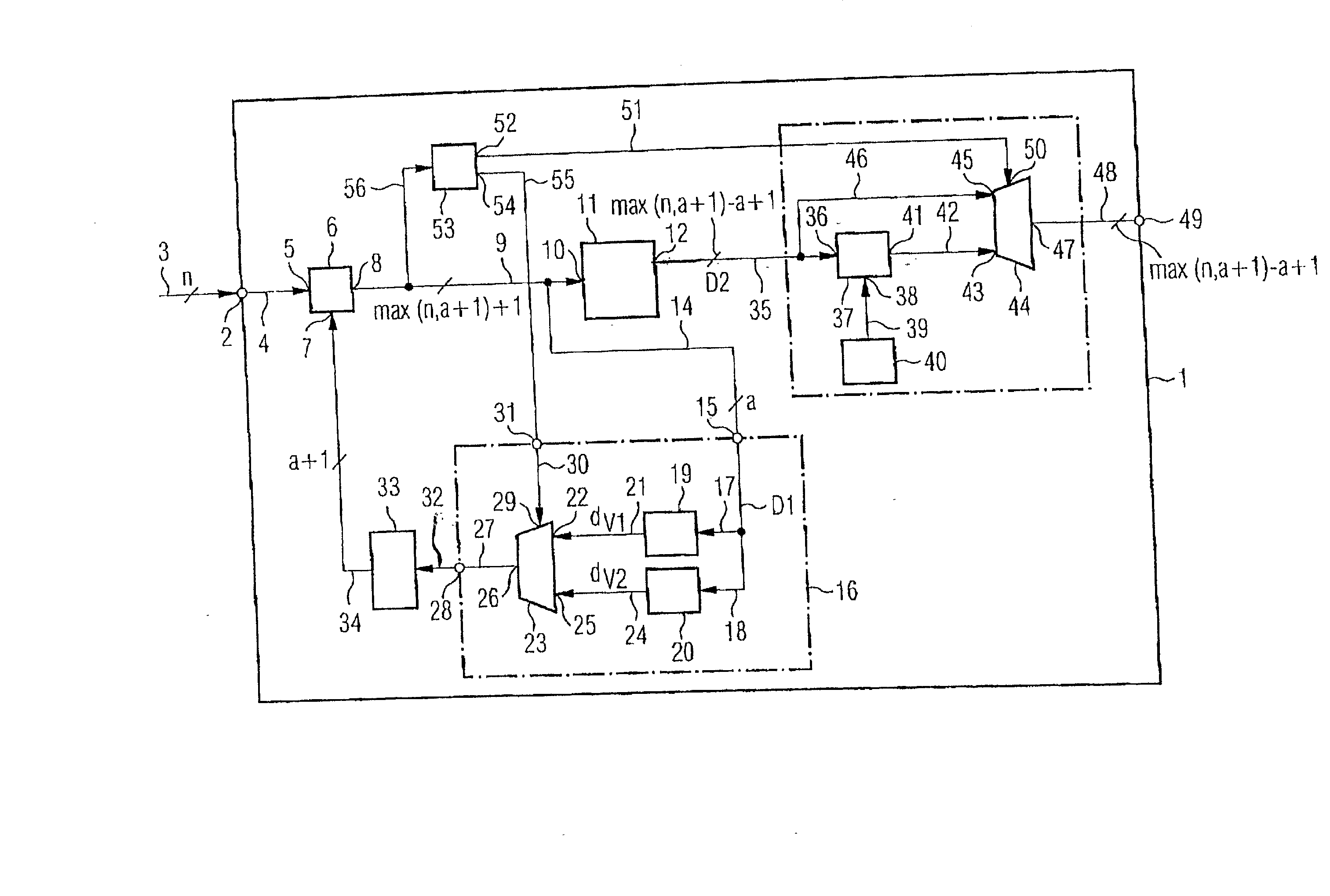
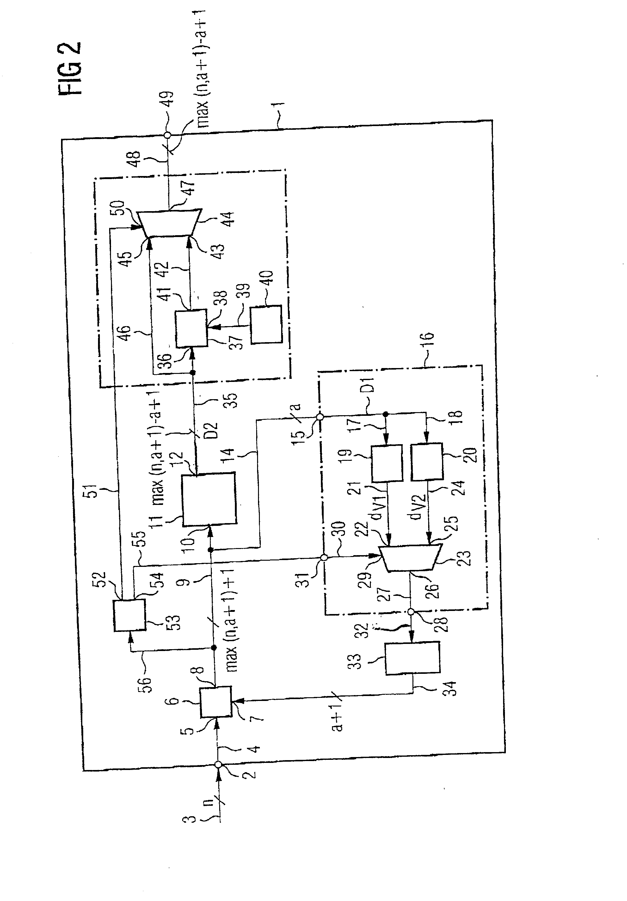
[0037] As can be discerned from FIG. 2, a calculation circuit 1 according to an embodiment of the present invention comprises a signal input 2 for applying a fixed-point input signal. The fixed-point input signal comprises a sequence of digital data values that have a width of n bits and are fed via n data lines 3 to the digital data input 2 of the calculation circuit 1 according to the invention. The signal input 2 is connected via data lines 4 to a first data input 5 of an adder 6. The adder 6 comprises a second data input 7 and adds the digital values present at the two data inputs 5,7 to form a first digital summation data value having a width of max (n, a+1)+1 bits. The first digital summation data value formed by the addition circuit 6 is output from an output 8 of the addition circuit 6 via data lines 9 to a digital data input 10 of a shift circuit 11. The shift circuit 11 comprises a signal output 12. The shift circuit 11 shifts the first summation data value present at the ...


PUM


Abstract

A calculation circuit for the division of a fixed-point input signal comprising a sequence of digital data values having a width of n bits by an adjustable division factor 2.sup.a for the purpose of generating a divided fixed-point output signal, having a signal input (2) for applying the data value sequence of the fixed-point input signal, a first addition circuit (6), which adds the digital data value present at the signal input (2) to a data value buffer--stored in a register (33) to form a digital first summation data value having a width of max (n, a+1) +1 bits, a shift circuit (11) which shifts the first summation data value present by a data bits toward the right, with the result that the max (n, a+1)-a+1 more significant data bits of the first summation data value are output at an output of the shift circuit (11), a logic circuit (16), which, as a function of the sign of the first summation data value, logically ANDs the a less significant data bits of the first summation data value with a logic combination data value, or logically Ors them with the inverted logical combination data value, and outputs them to the register (33) for buffer-storage of the logically combined data value (d.sub.v1, d.sub.v2), a second addition circuit (37), which, as a function of the sign of the first summation data value adds the data value output by the shift circuit (11) to a value one for eliminating the DC signal component to form a second summation data value, and having a signal output for outputting the sequence of the second summation data values as divided fixed-point output signal.

Description

CROSS-REFERENCE TO RELATED APPLICATION[0001] This application claims priority to German Patent Application No. DE 100 55 659.0, filed on Nov. 10, 2000.BACKGROUND[0002] 1. Technical Field[0003] The invention generally relates generally to a calculation circuit and method for the division of a fixed-point input signal and, in particular, to a circuit and method for dividing a digital fixed-point input signal by an adjustable division factor 2.sup.a for generating a divided fixed-point output signal that comprises minimal variance.[0004] 2. Discussion of Related Art[0005] DE 690 30 772 T2 describes a divider for high-speed execution of an arithmetic operation. The divider serves for generating a quotient by dividing a dividend by a divisor. A first holding device contains the dividend data characterizing the dividend. A second holding device contains the divisor data characterizing the divisor. An operation device generates either a sum or a difference between the dividend data and the...

Claims


Application Information

Patent Timeline
IPC IPC(8): G06F7/535H03M7/36
CPCG06F7/535G06F2207/5352
Inventor CLAUSEN, AXELHARTENECK, MORTITZ
Owner MAXLINEAR INC
Why Eureka
Try Eureka