Method for determining the distance between a transmitter and a receiver

a distance and receiver technology, applied in the field of determining the can solve the problems of affecting the multipath delay determined by the ranging code, and increasing the noise variance, so as to achieve the effect of more reliable position of a receiver

Inactive Publication Date: 2014-01-07
DEUTSCHES ZENTRUM FUER LUFT & RAUMFAHRT EV
View PDF2 Cites 0 Cited by
  • Summary
  • Abstract
  • Description
  • Claims
  • Application Information

AI Technical Summary

Benefits of technology

[0008]The present invention provides a method for determining a more reliable position of a receiver, when the signals are potentially affected by the ionosphere, multipath, and other phenomena that draw an advantage out of smoothing, wherein the receiver uses signals on at least three different frequencies.
[0018]wherein parameters describing the linear combination of the at least three coded signals and the first and second combinations of the at least three phase shifts are chosen such that (i) a combination of the ambiguities of the first and second combined phase shift signals result in a single ambiguity expressed as an integer multiplicity of an analytic combined wavelength, (ii) the noise variance is reduced, and (iii) the ratio of the single ambiguity and the noise variance is increased,
[0024]The present invention is based on the idea to use linear combinations of at least three carrier signals before and after the filtering of the code signal. Better than state of the art results are obtained, when the carrier combinations before and after the filter are the same, and both the code and carrier combinations are geometry preserving, ionosphere free, and optimized to achieve a minimum variance. This can be further improved by allowing the combination before and after the filter to be different. However, this introduces an integer ambiguity between the phase signal combination used before and after the filter, which must be estimated in addition to the position, and the offset of the local clock. There is some freedom in the choice of the linear combination, which is used to maximize the wavelength associated with the difference of the linear combination before and after the filtering. This greatly simplifies the estimation of the ambiguity. One possible implementation is to setup a linear equation describing for the linear combination considered and another ionosphere free smoothed solution, which uses the same carrier combinations before and after the filter. This system of equations can be solved by the least square method. The non-integer approximations of the ambiguities are then rounded to the nearest integer. The resulting probability of wrong detection is rather low, and the variance of the position also.
[0025]By introducing a further linear combination of the at least three phase shifts a system of equations is created which is over-determined so that the chose of the parameters used for the linear combinations for obtaining the pseudo range signal and the first and second combined phase shift signals can be optimized. One of the conditions for the first and second combined phase shift signals is that they include exactly the same distance information at the same point of time. Another condition is that the combination of the ambiguities of the frequencies results in a single ambiguity expressed in an integer multiplicity of an analytic combination wavelength. Accordingly, the signal resulting from the addition of the second combined phase shift signal to the filtered signal still includes ambiguities. However, when choosing the parameters of the linear combinations such that the combination wavelength is rather high and, in particular, the ratio of the combination wavelength and the noise variance is rather high, resolving the ambiguity is facilitated.

Problems solved by technology

The code phase, i.e., the delay determined by the ranging code is rather affected by multipath and is also rather noisy.
The problem in satellite navigation is that due to disturbance in the ionosphere unexpected and unforeseeable stochastic delays occur.
All code combinations considered so far have, however, increased the noise variance.
Due to this increased noise variance, the known carrier smoothing concepts cannot be used for high security applications like navigation of an aircraft during late final approach and landing phase.

Method used


Image

  • Method for determining the distance between a transmitter and a receiver
  • Method for determining the distance between a transmitter and a receiver
  • Method for determining the distance between a transmitter and a receiver

Examples


Embodiment Construction

1. Introduction

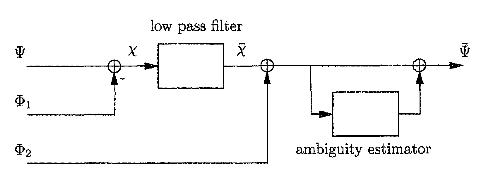
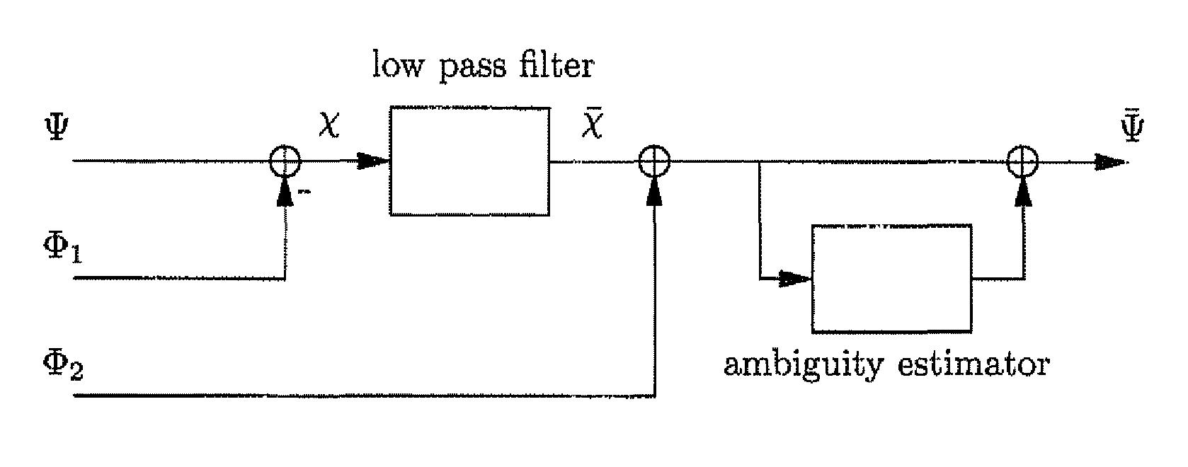
[0042]The smoothing of ranging codes using carrier signals is a popular approach to reduce code noise and code multipath. It was introduced by Hatch and is used in the Wide Area Augmentation System (WAAS), as well as in the European Geostationary Navigation Overlay Service (EGNOS). It is also considered for Ground Base Augmentation Systems (GBAS). Traditional code smoothing has the inconvenience that the ionospheric delay affects the code and carrier phase with opposite signs. Long smoothing intervals and large ionospheric delays are correspondingly both critical factors when applying this method. Two alternative approaches address this issue. They are based on dual-frequency measurements and were introduced by Hwang et al. and Mc. Graw et al. They are called ionospheric-free and divergence-free smoothing, respectively. The availability of an aeronautical CAT III type of navigation service using these smoothing approaches was analyzed by Konno et al. Their analysis sh...


PUM


Abstract

The present invention relates to a multiple carrier smoothing method for navigation satellite signals, in particular a three carrier smoothing method for Galileo signals. It provides a smoothed code solution, which is ionosphere-free to the first order and whose noise is reduced to sub-decimeter level. The method involves integer ambiguities, which can be resolved reliably. The sensitivity of the new method to receiver biases and ionospheric delays of the second order is small. The performance of the three carrier smoothing method allows to reduce the averaging interval to ⅕-th of its current standard value. The results refer to pseudo ranges and are geometry independent.

Description

[0001]This application is a national phase of International Application No. PCT / EP2008 / 063016 filed Sep. 29, 2008 and published in the English language.BACKGROUND[0002]The present invention relates to a method for determining the position of a receiver using signals transmitted, e.g. by a constellation of satellites. The receiver is typically located at low altitudes. In particular, the receiver can be located in an aircraft for navigating during final approach and even for landing the aircraft, in a ship or a vehicle moving over ground. More particularly, the present invention relates to a reduced-noise ionosphere-free smoothing of ranging codes.[0003]Satellite navigation is part of nowadays daily life and is used for an increased number of applications. The signals transmitted by the satellites and received by receivers comprise at least one ranging code modulated on at least one carrier. The ranging code is a sequence of binary values, called chips. The rate of the ranging code i...

Claims


Application Information

Patent Timeline
Patent Type & Authority Patents(United States)
IPC IPC(8): G01S19/44G01S19/43G01S5/14G01S19/32
CPCG01S19/32G01S19/15G01S19/44
Inventor GUENTHER, CHRISTOPH
Owner DEUTSCHES ZENTRUM FUER LUFT & RAUMFAHRT EV
Why Eureka
Try Eureka