
Method and apparatus for coating balloon catheters

a balloon catheter and coating technology, applied in the direction of balloon catheters, coatings, catheters, etc., can solve the problems of coating inaccuracy, affecting the coating process, and compromising the function of the device, so as to improve the coating process of the balloon catheter, prevent unsteady or wobbly rotation of the balloon, and precise positioning

Active Publication Date: 2015-06-25
SURMODICS INC
View PDF8 Cites 2 Cited by
  • Summary
  • Abstract
  • Description
  • Claims
  • Application Information

AI Technical Summary

Benefits of technology

The apparatus provides a uniform and precise coating on the balloon catheter surface, preventing unsteady rotation and allowing for rapid loading and removal of pre-inflated catheters, while minimizing extraneous coating flux and ensuring consistent coating quality.

Problems solved by technology

However, various challenges exist for the design and use of coating apparatus designed to provide coatings to medical devices.
Traditional coating methods, such as dip coating, are often undesirable as they may result in flawed coatings that could compromise the function of the device or present problems during use.
These methods can also result in coating inaccuracies, which can be manifested in variable amounts of the coated material being deposited on the surface of the device.
It has been difficult to achieve a great degree of accuracy using traditional coating methods and machines.
As another challenge, implantable or insertable medical devices are typically small and often have unusual, complex configurations.
As a general matter, the handing of these devices in an appropriate manner during a coating procedure is often challenging.
It is often difficult to fixture and manipulate the devices so they receive a desired coating of material.
It is also often difficult to prevent the coating apparatus and method from introducing defects into the formed coating.
The balloon is then inflated when the catheter reaches target site resulting in application of mechanical force sufficient to cause vessel dilation.
Applicants have found that the complex design of a balloon catheter has made the balloon portion of the catheter difficult to coat.

Method used


Image

  • Method and apparatus for coating balloon catheters
  • Method and apparatus for coating balloon catheters
  • Method and apparatus for coating balloon catheters

Examples


Embodiment Construction

[0028]The embodiments of the present invention described herein are not intended to be exhaustive or to limit the invention to the precise forms disclosed in the following detailed description. Rather, the embodiments are chosen and described so that others skilled in the art can appreciate and understand the principles and practices of the present invention.

[0029]All publications and patents mentioned herein are hereby incorporated by reference. The publications and patents disclosed herein are provided solely for their disclosure. Nothing herein is to be construed as an admission that the inventors are not entitled to antedate any publication and / or patent, including any publication and / or patent cited herein.

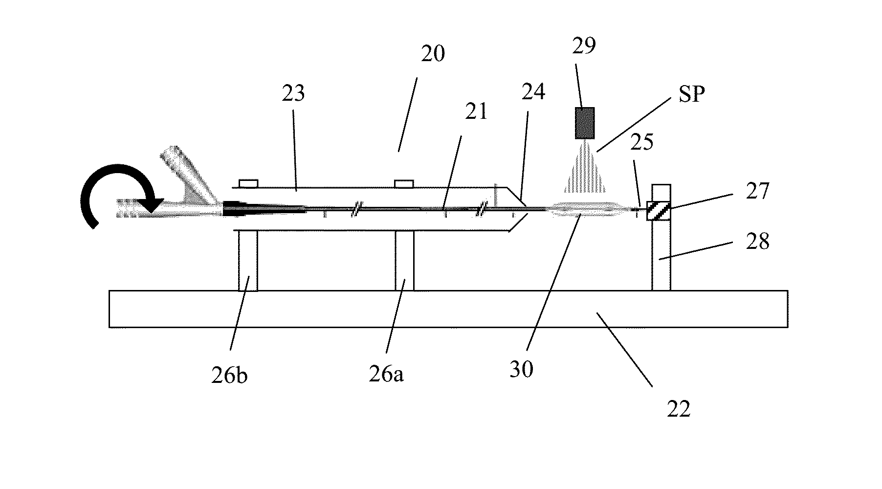
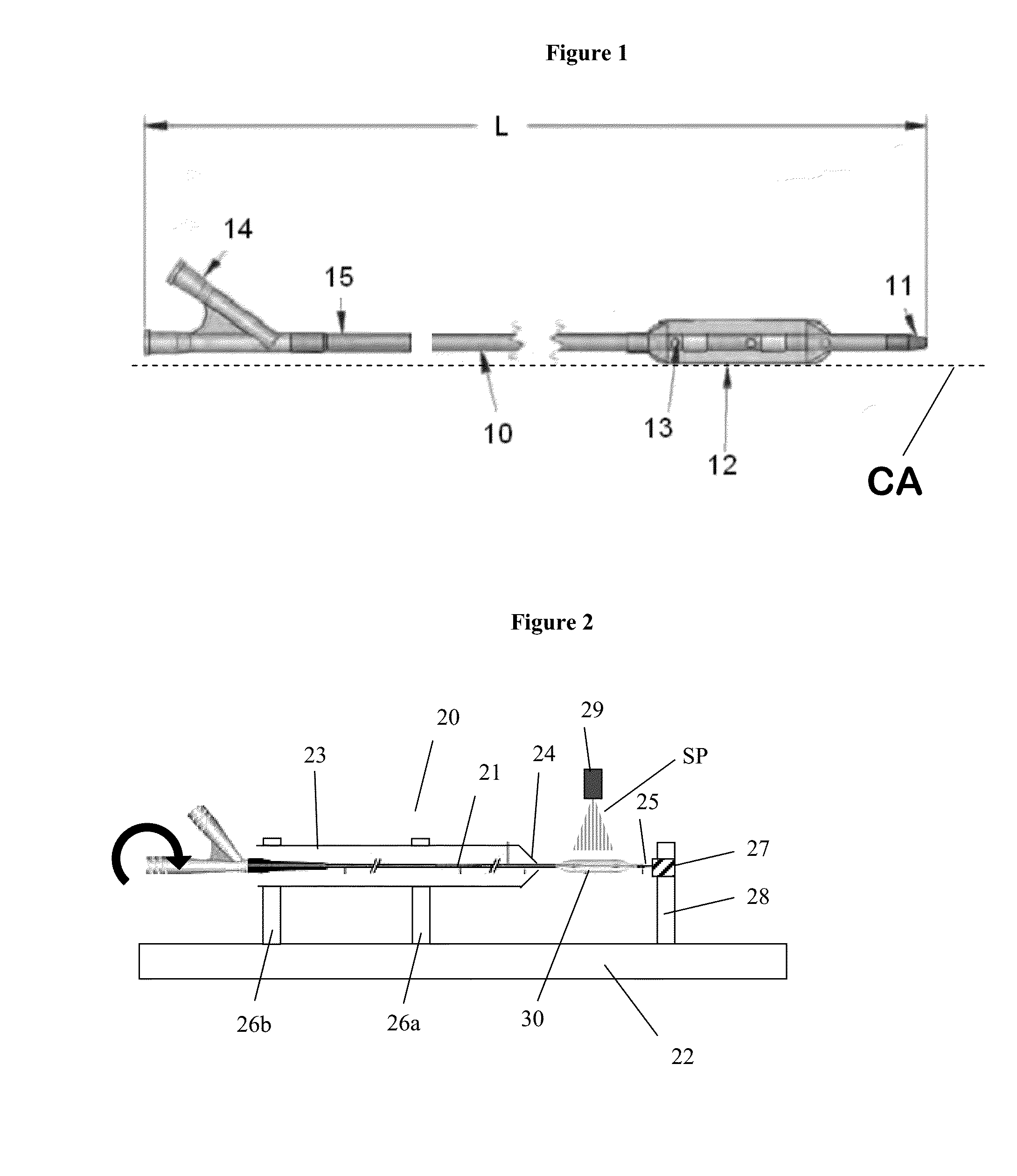
[0030]One aspect of the present invention relates to an apparatus for coating a balloon catheter. The apparatus includes a rotatable member, a support member, and a spray nozzle. The rotatable member and support member are arranged along the same axis of rotation (herein refe...


PUM


Abstract

A coating apparatus for coating the balloon portion of a balloon catheter is described. The coating apparatus includes a rotatable member in which the catheter portion of the balloon catheter is mounted and fixed, and which causes rotation of the balloon catheter. The apparatus also includes a support member in which the distal tip of the catheter is inserted and free to rotate; and a spray nozzle directing sprayed material on the balloon surface. The inventive configuration of the coating apparatus allows the balloon catheter to be rotated along its axis with insubstantial or no wobble, which significantly improves the quality of the coating applied to the surface of the balloon.

Description

CROSS-REFERENCE TO RELATED APPLICATION[0001]This application is a continuation of application Ser. No. 12 / 583,112, filed Aug. 14, 2009, which claims priority under 35 U.S.C. §119(e) from U.S. Provisional Patent Application having Ser. No. 61 / 188,929, filed on Aug. 14, 2008, and titled METHOD AND APPARATUS FOR COATING BALLOON CATHETERS, wherein the entirety of said patent applications are incorporated herein by reference.FIELD OF THE INVENTION[0002]The invention relates to a spray coating apparatus and methods for disposing a coating material on a medical device surface.BACKGROUND OF THE INVENTION[0003]Functional improvements to implantable or insertable medical devices can be achieved by coating the surface of the device. For example, a coating formed on the surface of the device can provide improved lubricity, improved biocompatibility, or drug delivery properties to the surface. In turn, this can improve movement of the device in the body, extend the functional life of the device,...

Claims


Application Information

Patent Timeline
Patent Type & Authority Applications(United States)
IPC IPC(8): A61M25/10B05D1/00B05C13/00
CPCA61M25/1029A61M2025/1031B05D1/002B05C13/00A61M25/1027B05B13/0214B05B13/0228B05D1/02A61M25/1018A61M2025/105B05D3/12
Inventor CHAPPA, RALPH A.CARLSON, MARK F.
Owner SURMODICS INC
Learn More