Data communication system with self-test facility

a data communication system and self-testing technology, applied in the field of data communication systems with self-testing facilities, can solve the problems of large overhead of 8b/10b coding imposing operational disadvantages when applied to 10 gb/s transmissions, unable to adequately test the error floor of the 2.sup.31-bit test sequen

Inactive Publication Date: 2002-09-12
KEYSIGHT TECH
View PDF5 Cites 41 Cited by
  • Summary
  • Abstract
  • Description
  • Claims
  • Application Information

AI Technical Summary

Problems solved by technology

The demand for additional communication bandwidth is severely stressing the capabilities of current electronic and optical technologies.
The large overhead of 8b / 10b coding imposes operational disadvantages when applied to 10 Gb / s transmissions.
As a result, a 2.sup.31-bit test sequence does not adequately test the error floor.
This would make it difficult to repeat a part of the test sequence that caused the data communication system to fail.
Another disadvantage of the conventional test sequence generator is that the test sequence looks like an error to any receiver in the data communication system not in self-test mode.
Some receivers may require significant time to recover from such an error state.
A further disadvantage is that the test sequence is introduced into the transmitter 20 downstream of the frame assembler 34, so that the test sequence does not test the synchronization acquisition capability of the demultiplexer 36.

Method used


Image

  • Data communication system with self-test facility
  • Data communication system with self-test facility
  • Data communication system with self-test facility

Examples


Embodiment Construction

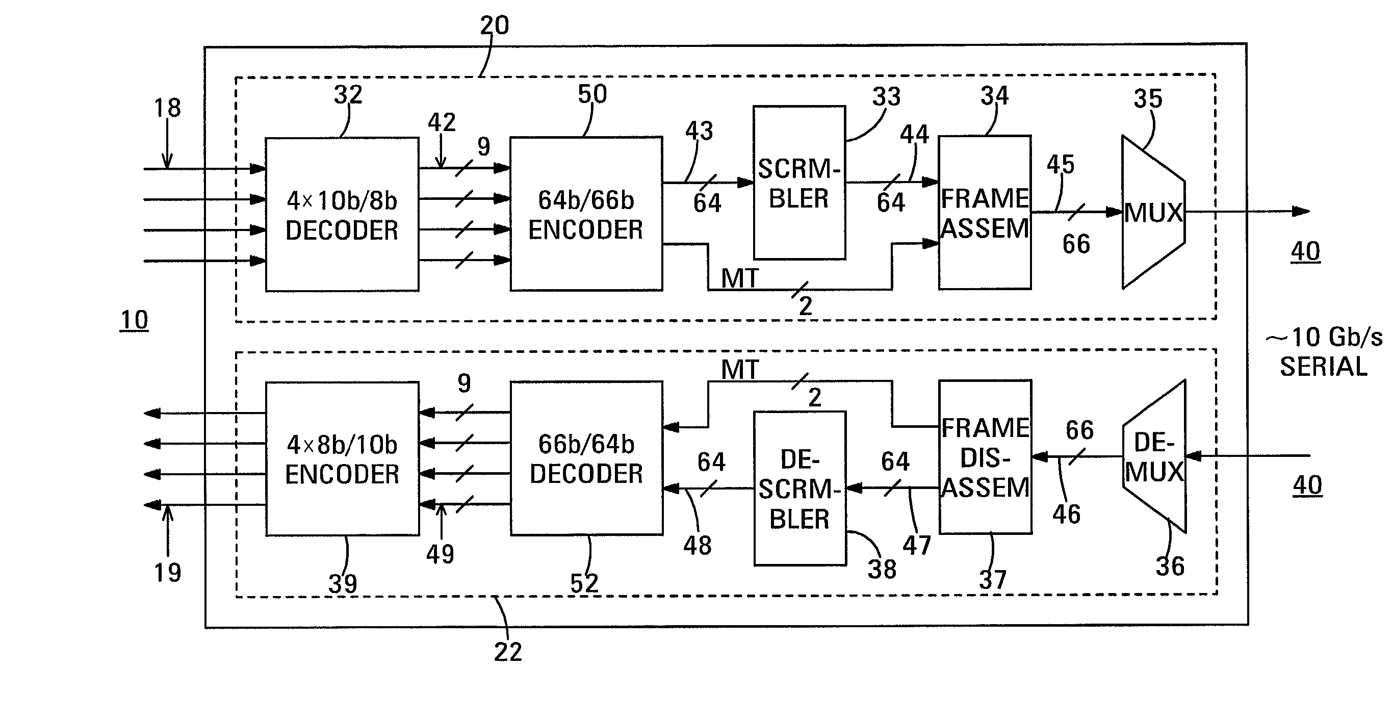
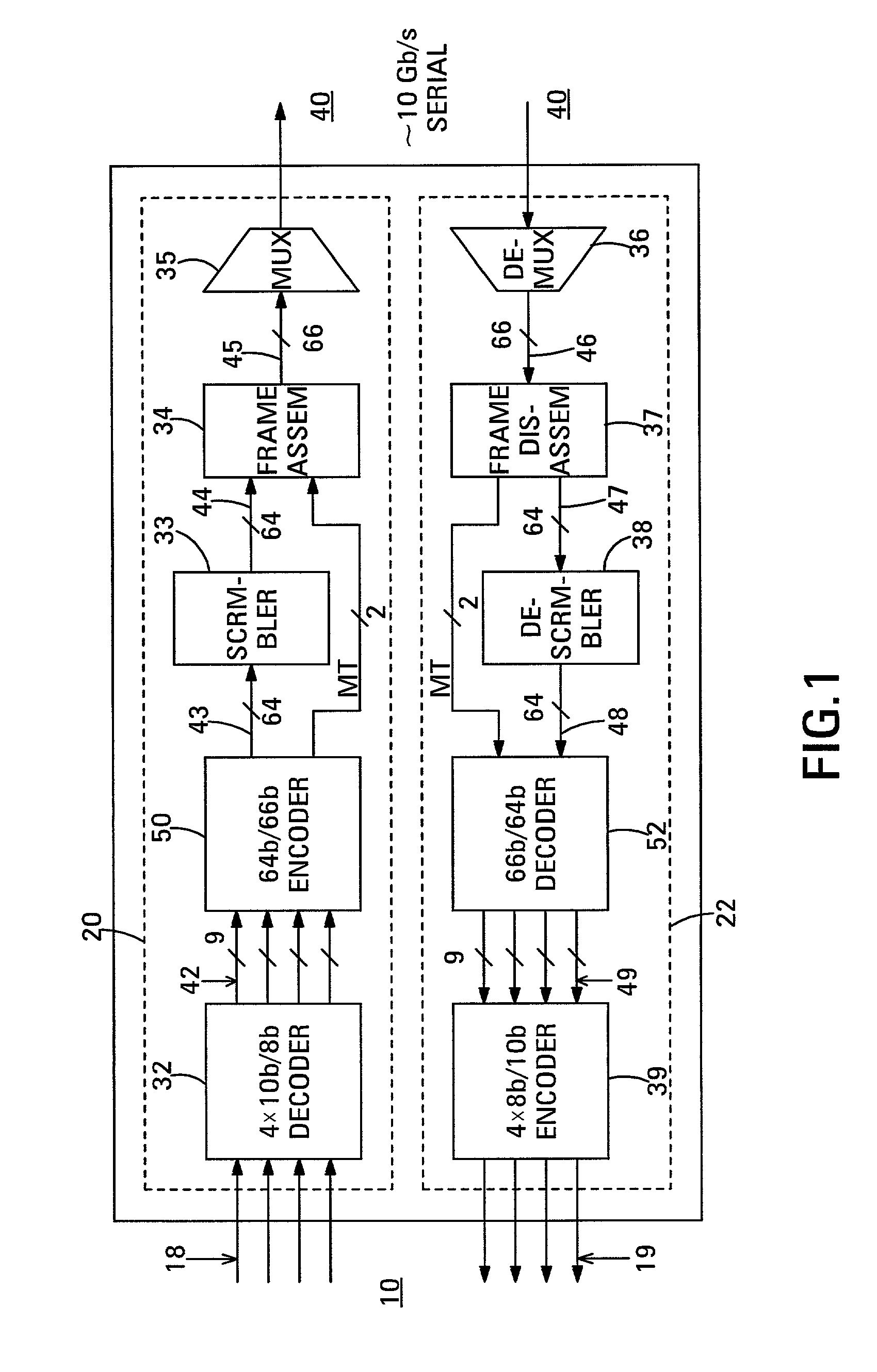
[0067] The invention is based on the observation that the test sequence generator 64 of the conventional bit error rate tester 61 shown in FIG. 3 has substantial circuit commonality with the scrambler 33 used to scramble the payload fields in the data communication system 60. The invention is based on the realization that, if the existing scrambler could be used to generate a test sequence, a self-test facility could be provided more simply and less expensively than the conventional approach shown in FIG. 3.

[0068] In a first aspect of the invention, in the self-test operating mode of the data communication system, the existing scrambler, e.g. the scrambler 33 shown in FIG. 1, is fed with a seed payload field. The existing scrambler is used in the normal operating mode to scramble the payload fields. The scrambler 33 scrambles the seed payload field to generate the fields of a test sequence. Each of the fields is filled with pseudo-random bits. A master transition is added to each fi...


PUM


Abstract

Self testing of a data communication system that includes a presettable scrambler and a complementary presettable descrambler is performed by presetting the presettable scrambler to a preset state. A seed payload field is scrambled using the presettable scrambler to generate fields of a test sequence. The fields of the test sequence are transmitted and corresponding received test sequence fields are received. The received test sequence fields are descrambled using the presettable descrambler to generate respective recovered test sequence fields. Differences between the recovered test sequence fields and the seed payload field are then detected as errors. A data communication system having a built-in self-test facility comprises a seed payload field source, a presettable scrambler, a presettable descrambler and an error detector. The presettable scrambler includes an input connected to the seed payload field source and an output coupled to a data transmission medium. The presettable scrambler is presettable to a preset state. The presettable descrambler includes an input coupled to the transmission medium and an output. The error detector includes an input connected to the output of the presettable descrambler, and operates to generate an error indication when a recovered test sequence field output by the presettable descrambler differs from the seed payload field.

Description

BACKGROUND OF THE INVENTION[0001] For several decades, integrated circuit and laser technologies have doubled in performance approximately every 18 months. These technologies have been used to support a rapidly-growing demand for global communications capacity. This demand is currently growing much faster than the underlying rate of improvement of the supporting technologies. As an example, communication traffic through the Internet has recently been doubling every nine months. The demand for additional communication bandwidth is severely stressing the capabilities of current electronic and optical technologies.[0002] In particular, the Ethernet local area network standard has progressively increased in speed by factors of ten, starting at 10 megabit per second (Mb / s) in 1982. Proposals for a 10 gigabit / second (Gb / s) Ethernet standard were made in 1999. The most recently adopted Ethernet standard is for transmitting serial data at 1 Gb / s and uses a 8b / 10b line code described by A. X...

Claims


Application Information

Patent Timeline
Patent Type & Authority Applications(United States)
IPC IPC(8): H04L1/24H04L69/40
CPCH04L1/242H04L1/244H04L1/203H04L1/241
Inventor WALKER, RICHARD C.THALER, PATRICIA A.
Owner KEYSIGHT TECH
Why Eureka
Try Eureka