Enclosure member, and multi-link conveyor chain

a conveyor chain and locking member technology, applied in the direction of conveyors, transportation and packaging, railway components, etc., can solve the problems of multi-link conveyor chain collapse, pin head wear and eventually shear off, and elongated pin dislocation,

Inactive Publication Date: 2002-09-19
PENNINE INDAL EQUIP
View PDF6 Cites 24 Cited by
  • Summary
  • Abstract
  • Description
  • Claims
  • Application Information

AI Technical Summary

Problems solved by technology

A disadvantage of this arrangement is that unless the guide strip adjacent to the multi-link conveyor chain is in perfect alignment with the edge of the multi-link conveyor chain, there is a tendency for the pin head to wear and eventually shear off so that the elongate pin may becomes dislodged.
In extreme cases, this results in total collapse of the multi-link conveyor chain.
This is due to the space constraints imposed on the second pin head by the non-circular aperture in the second enclosure member.

Method used


Image

  • Enclosure member, and multi-link conveyor chain
  • Enclosure member, and multi-link conveyor chain
  • Enclosure member, and multi-link conveyor chain

Examples


Embodiment Construction

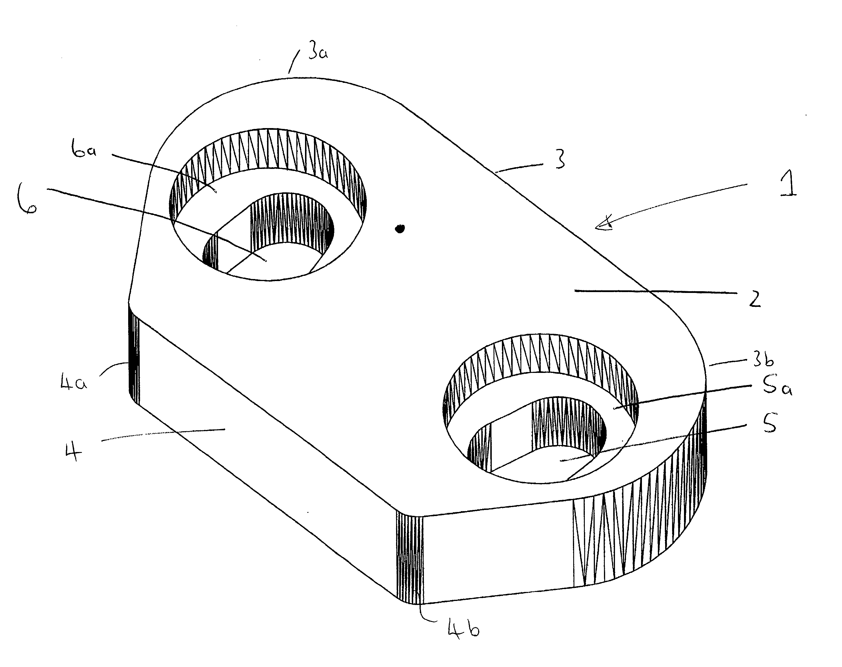
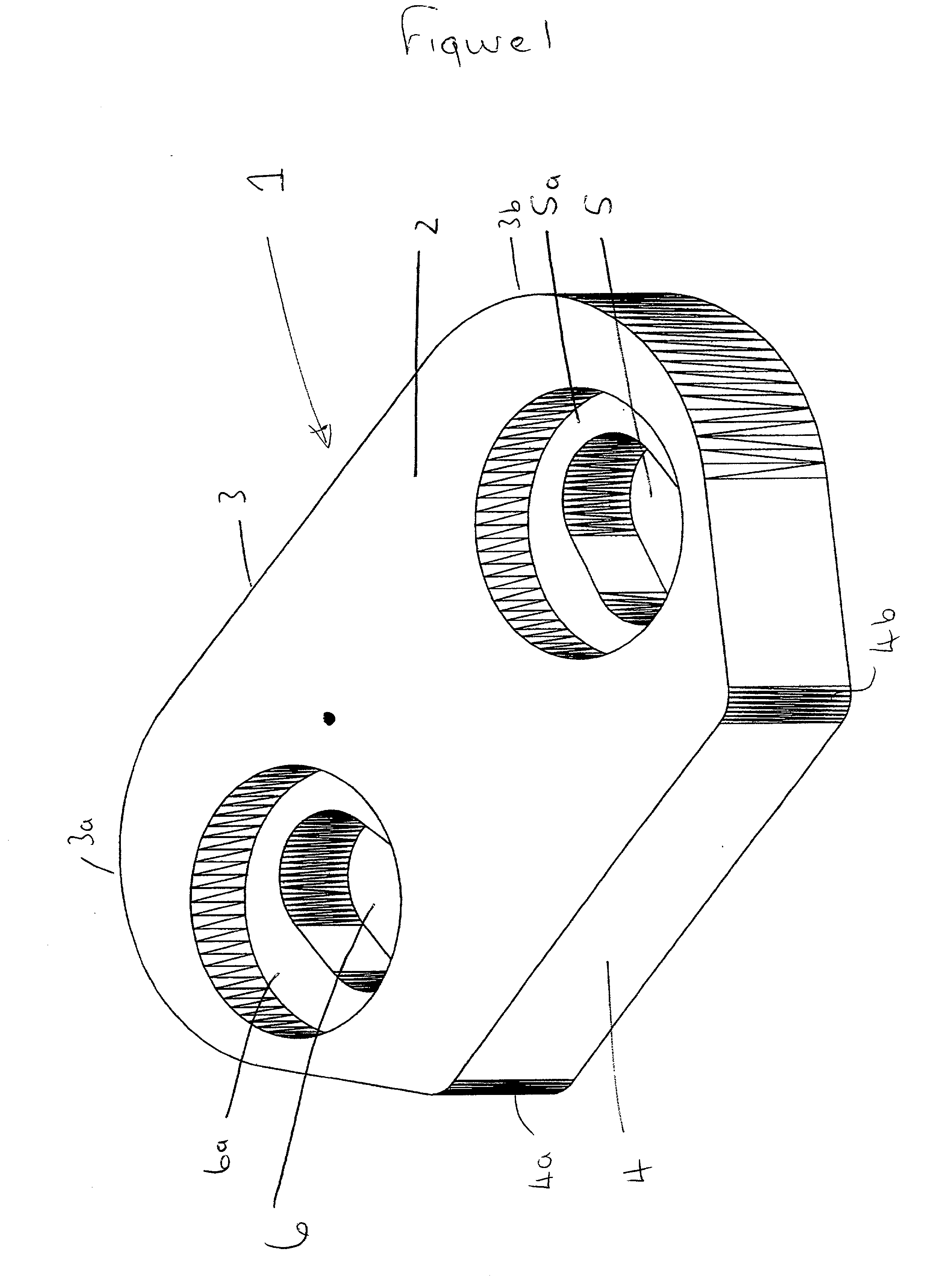
[0051] FIG. 1 illustrates an embodiment of the enclosure member of the invention designated generally by reference numeral 1. The enclosure member 1 comprises a trapezoidal main body 2 having a long side 3 parallel to a short side 4. The corners 3a and 3b of the long side 3 are rounded off (and to a lesser extent so are the corners 4a and 4b of the short side 4). The main body 2 defines a first non-circular aperture 5 and a second non-circular aperture 6, each of which are elliptical and provided with a cylindrical counterbore 5a and 6a respectively.

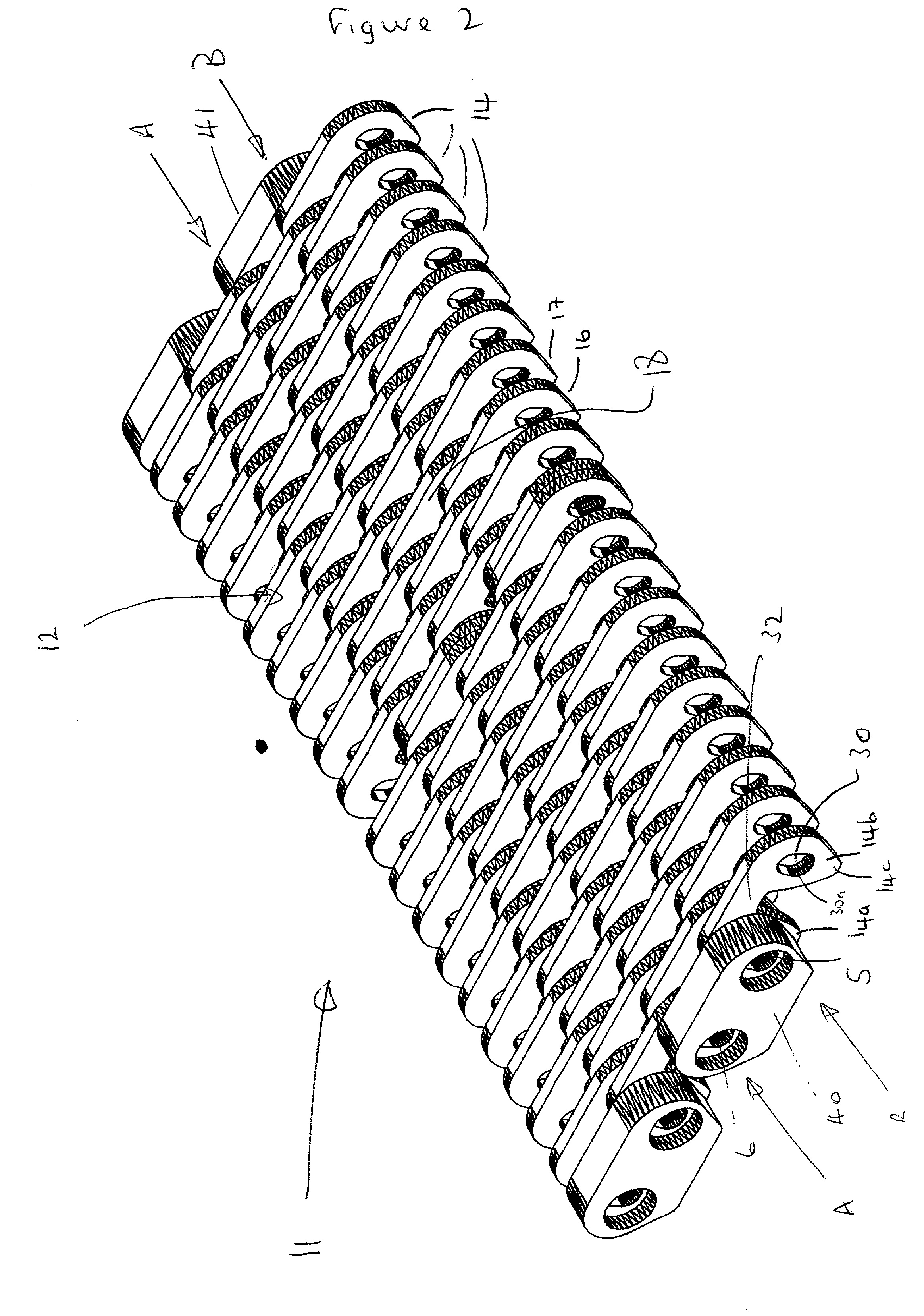
[0052] FIG. 2 illustrates in partial view an embodiment of the multi-link conveyor chain of the invention designated generally by reference numeral 11. For the sake of clarity, the elongate pins and washers are omitted from FIG. 2 (nevertheless it will be readily apparent how and where these are used).

[0053] The multi-link conveyor chain 11 provides a flat surface 12 upon which may be carried articles such as glass bottles to a processin...


PUM


Abstract

The present invention relates to a multi-link conveyor chain which may be used (for example) in the glass industry, in particular to an enclosure member for protecting the integrity of the multi-link conveyor chain during use and to a method for manufacturing the multi-link conveyor chain incorporating the enclosure member.

Description

[0001] This application claims the benefit of priority of foreign patent application 0106190.2 filed in the United Kingdom on Mar. 14, 2001, the complete disclosure of which is incorporated herein by reference.[0002] 1. Field of the Invention[0003] The present invention relates to a multi-link conveyor chain which may be used (for example) in the glass industry, in particular to an enclosure member for protecting the integrity of the multi-link conveyor chain during use and to a method for manufacturing the multi-link conveyor chain incorporating said enclosure member.[0004] 2. Description of the Related Art[0005] Multi-link conveyor chains are in widespread use in the glass industry for transporting glass products between processing stations. For example, a multi-link conveyor chain which is typically 100 feet long may be used to transport blown glass from a blowing station to an annealing station. In the conventional multi-link conveyor chain, there is a plurality of parallel spac...

Claims


Application Information

Patent Timeline
Patent Type & Authority Applications(United States)
IPC IPC(8): B65G17/08B65G17/38
CPCB65G17/08B65G17/38B65G2201/02
Inventor MARSHALL, CHRISTOPHER
Owner PENNINE INDAL EQUIP
Why Eureka
Try Eureka