Power tool and spindle lock system

a technology of spindle lock and power tool, which is applied in the direction of power-driven tools, couplings, interlocking clutches, etc., can solve the problems of increased problems, damage to components, and large "clunks" of the spindle, and achieve quiet stopping of the spindle and discharging the spinning energy

Inactive Publication Date: 2002-09-19
DAIJIRO NAKAMURA +1
View PDF3 Cites 73 Cited by
  • Summary
  • Abstract
  • Description
  • Claims
  • Application Information

AI Technical Summary

Benefits of technology

0014] One independent advantage of the present invention is that stopping of the motor and automatic locking of the spindle can be done quietly without producing the impact or "clunk" accompanied by the sudden engagement of the spindle lock. The resilient force of the spring element of the spindle rotation controlling structure buffers and controls the rotation of the spindle caused by the inertia of the spindle (and tool holder and/or supported tool element). This resilient force also buffers and controls the inertia of the spindle when there is little or no relative rotation between the spindle and the driving engagement with the motor.
0015] Another independent advantage of the present invention is that, even if the inertia of the spindle, tool holder and supported tool element is greater than the resilient force of the spring element of the spindle rotation controlling structure (such th

Problems solved by technology

One independent problem with the above-identified automatic spindle locks is that, when the motor is switched from an operating condition, in which the spindle is rotatably driven, to a non-operating condition, the inertia of the still-rotating spindle (and tool holder and/or supported tool element) causes the automatic spindle lock to engage to stop the rotation of the spindle relative to the motor within the free angle of rotation between the spindle and the motor.
The engagement of the spindle lock can be sudden, causing an impact in the components of the spindle lock, resulting in noise (a big "clunk") and, potentially, damage to the components.
This problem is increased the greater the inertia acting on the spindle (i.e., with larger tool elements, such as hole

Method used


Image

  • Power tool and spindle lock system
  • Power tool and spindle lock system
  • Power tool and spindle lock system

Examples


Embodiment Construction

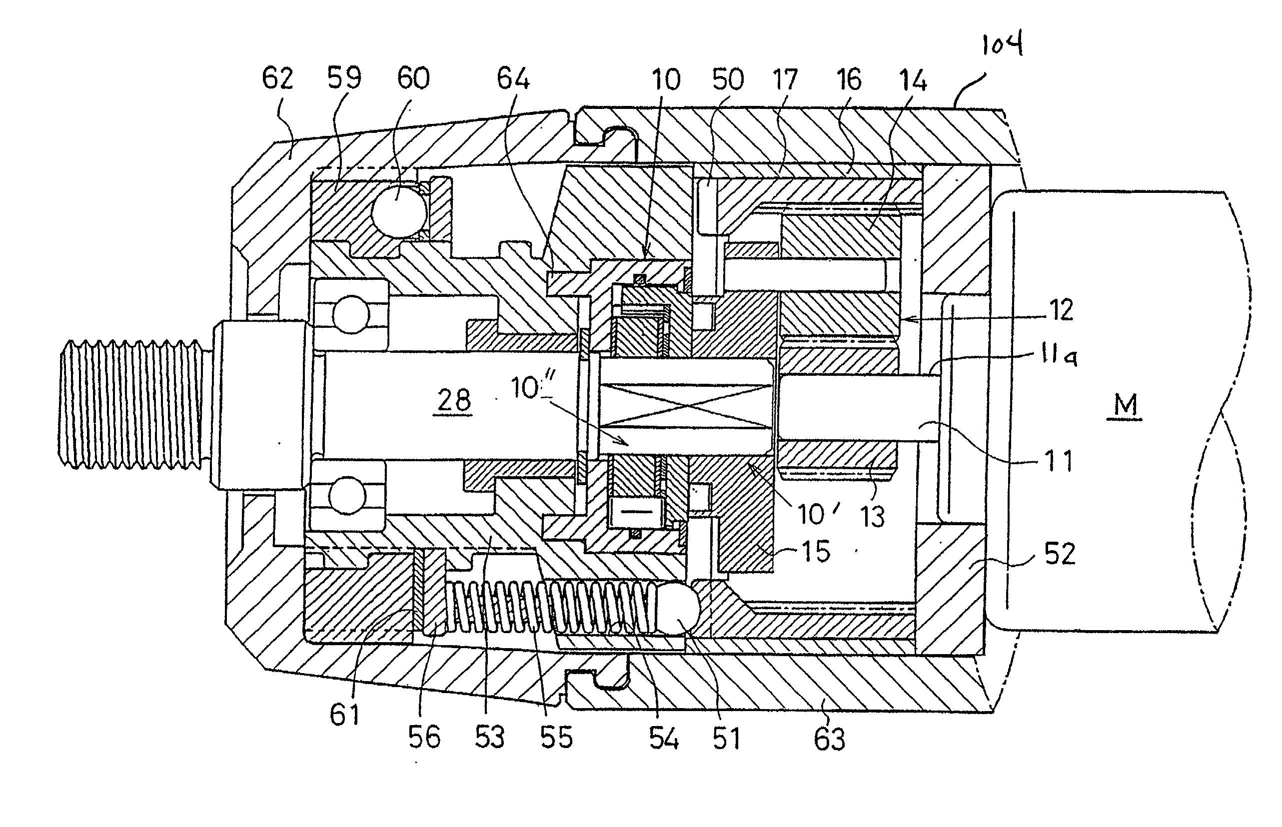
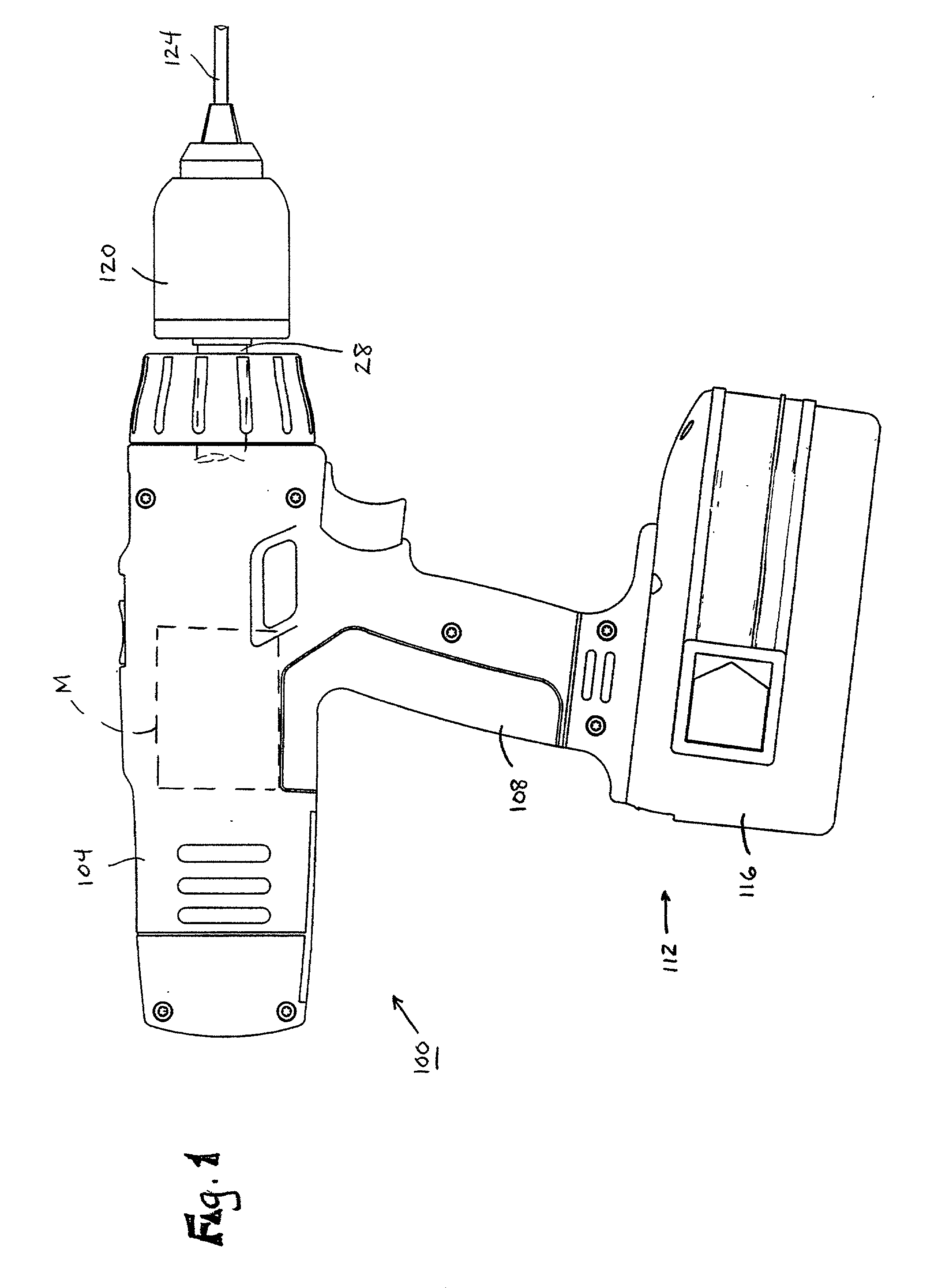
[0038] FIG. 1 illustrates a power tool 100 including (see FIG. 3) a spindle lock system 10 embodying the invention. As shown in FIG. 1, the power tool 100 includes a housing 104 having a handle 108 to be gripped by an operator during operation of the power tool 100. A motor M (schematically illustrated) is supported by the housing 104, and a power source 112, such as, in the illustrated construction, a battery 116, is connectable to the motor M by an electrical circuit (not shown) to selectively power the motor M.

[0039] The power tool 100 also includes a spindle 28 rotatably supported by the housing 104 and selectively driven by the motor M. A tool holder or chuck 120 is supported on the forward end of the spindle 28 for rotation with the spindle 28. A tool element, such as, for example, a drill bit 124, is supported by the chuck 120 for rotation with the chuck 120.

[0040] In the illustrated construction, the power tool 100 is a drill. It should be understood that, in other construct...


PUM


Abstract

A power tool and spindle lock. The spindle lock includes a spring and a detent arrangement to control and buffer the rotation of the spindle and to delay the engagement of the locking elements. In some aspects, the invention provides a spindle lock including a spring element which applies substantially equal spring force to delay the operation of the spindle lock when the spindle is rotated in the forward direction or in the reverse direction. In some aspects, the invention provides two spring members which cooperate to apply the substantially equal force to delay the operation of the spindle lock when the spindle is rotated in the forward direction or in the reverse direction.

Description

RELATED APPLICATIONS[0001] The present application is a continuation-in-part of co-pending application Ser. No. 09 / 995,256, filed Nov. 27, 2001.FIELD OF THE INVENTION[0002] The invention relates to power tools and, more particularly, to a spindle lock system for a power tool.BACKGROUND OF THE INVENTION[0003] A typical electric machine, such as a rotary power tool, includes a housing, a motor supported by the housing and connectable to a power source to operate the motor, and a spindle rotatably supported by the housing and selectively driven by the motor. A tool holder, such as a chuck, is mounted on the forward end of the spindle, and a tool element, such as, for example, a drill bit, is mounted in the chuck for rotation with the chuck and with the spindle to operate on a workpiece.[0004] To assist the operator in removing and / or supporting the tool element in the tool holder, the power tool may include a spindle lock for preventing rotation of the spindle relative to the housing w...

Claims


Application Information

Patent Timeline
IPC IPC(8): B25B21/00B25F5/00
CPCB25B21/00B25F5/001
Inventor NAKAMURA, DAIJIROKLEMM, ROBERT W.
Owner DAIJIRO NAKAMURA
Why Eureka
Try Eureka