
Transformer winding

Inactive Publication Date: 2002-09-19
ABB RES LTD
View PDF0 Cites 5 Cited by
  • Summary
  • Abstract
  • Description
  • Claims
  • Application Information

AI Technical Summary

Benefits of technology

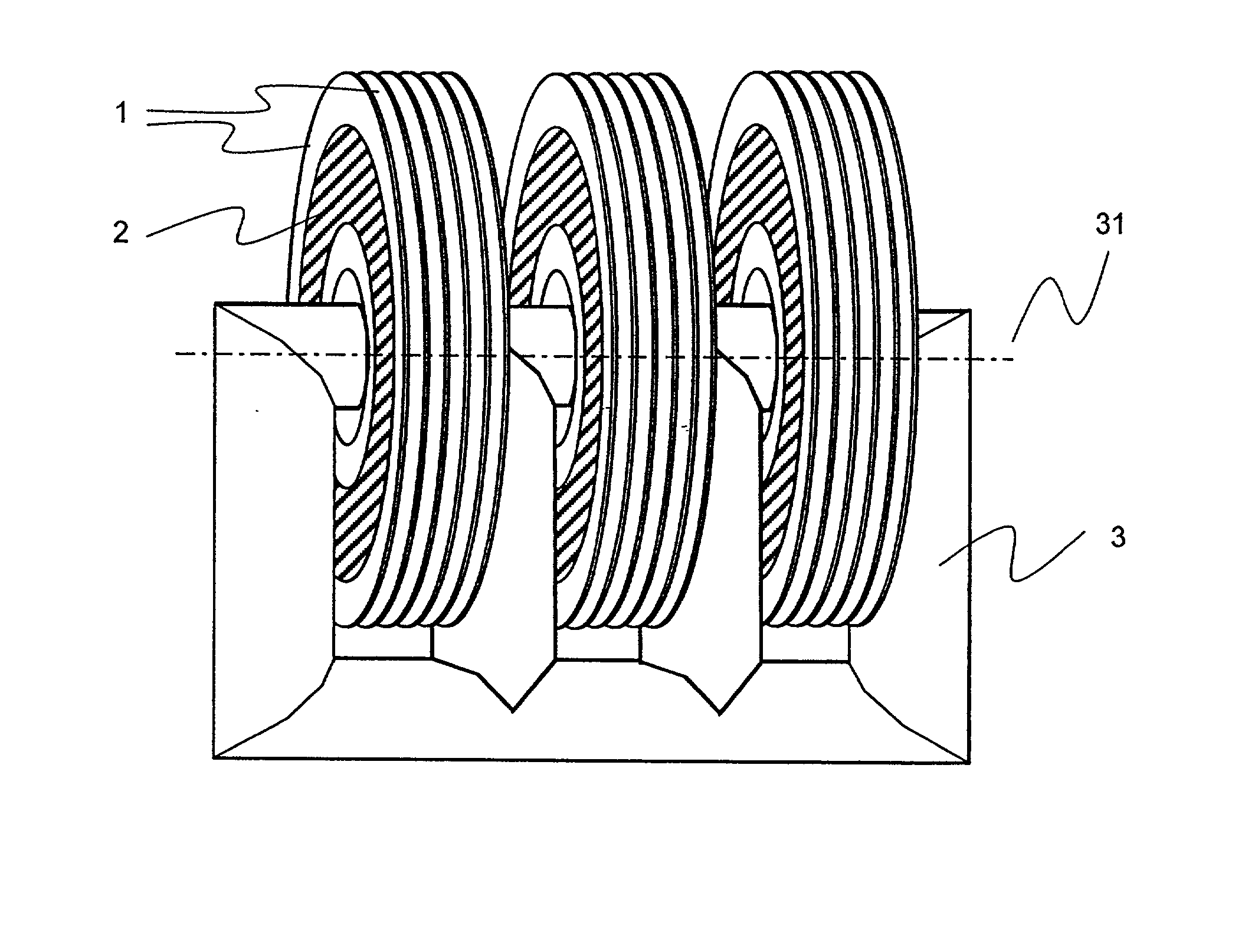
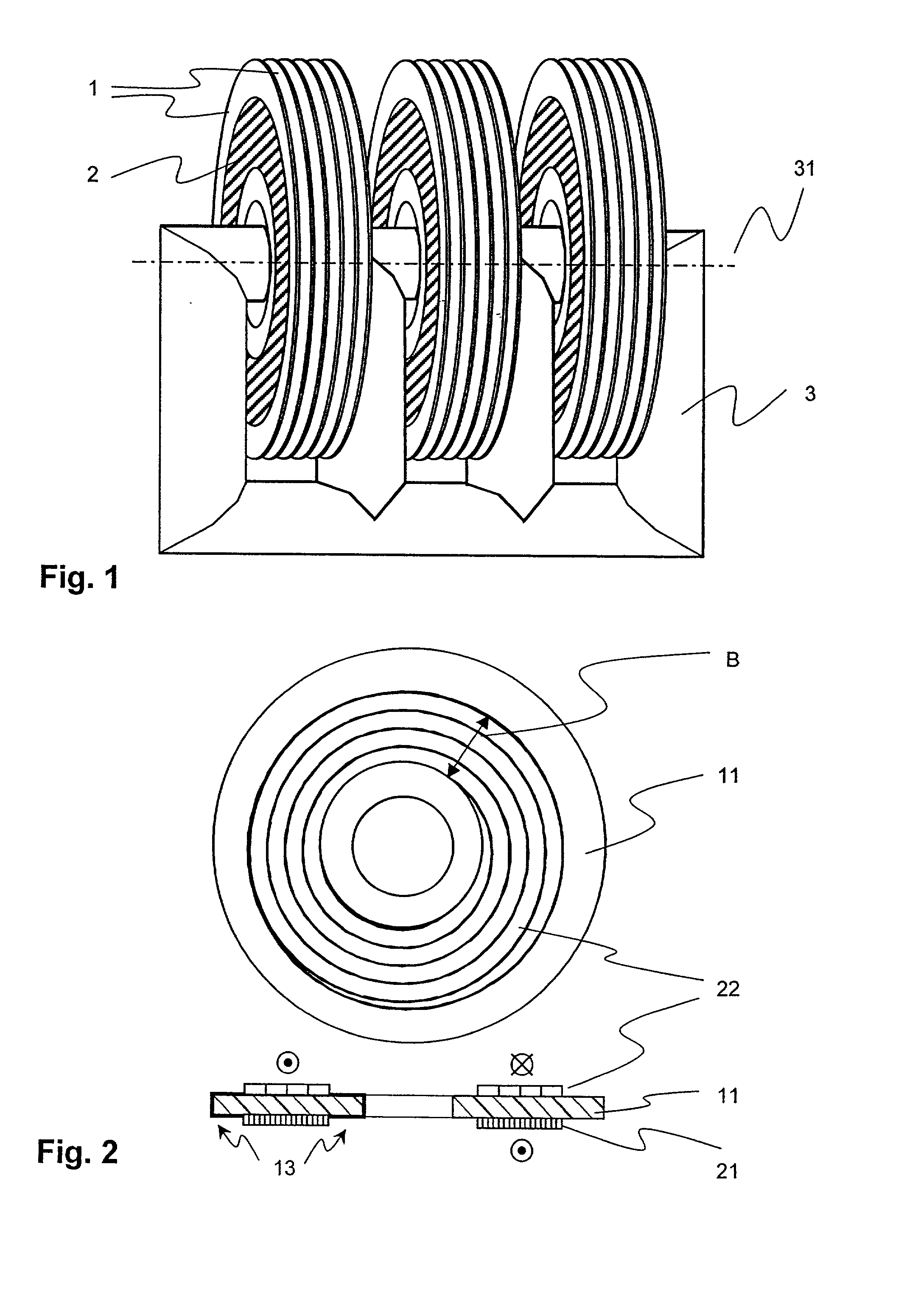
[0006] The essence of the invention is to construct a transformer winding composed of planar conductor tracks, which are arranged following one another and are separated from one another by suitable spacing and insulation elements. This modular transformer construction avoids the need for the labor-intensive winding process with the conventional conductor wire.
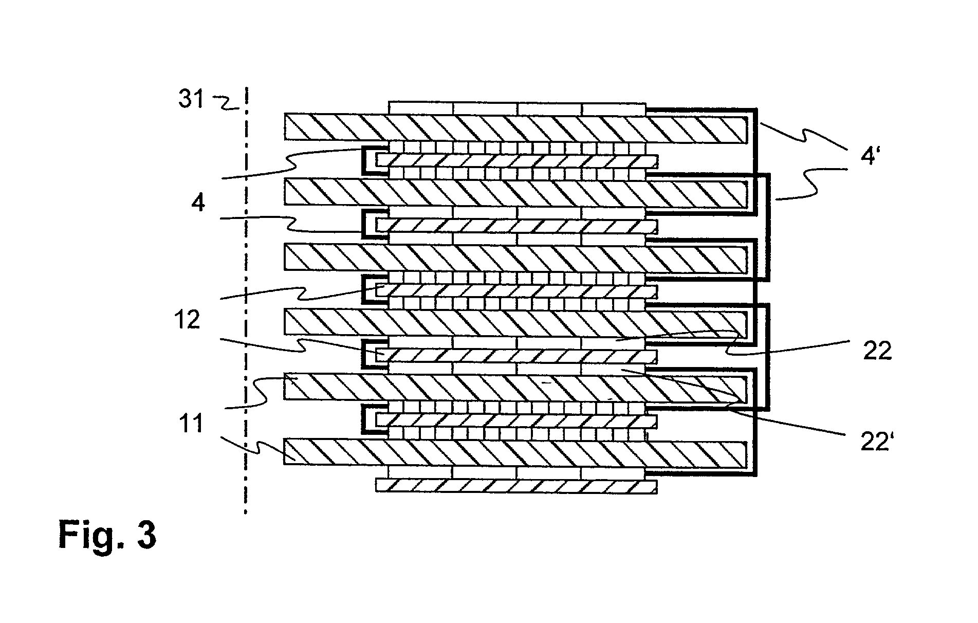
[0007] The proposed transformer concept is based on a production process which, in two steps, first of all comprises the fabrication of the turns and then their assembly to form the transformer, hence combining automation potential and flexibility. Both the high-voltage winding and the low-voltage winding are formed from effectively two-dimensional, preferably spiral conductor tracks. These conductor tracks each have at least one turn, and the corresponding structure can be produced by machine. The conductor tracks are then arranged in the desired sequence, and are electrically connected to form a winding. Insulation and spacing elements are inserted between the conductor tracks and, firstly, provide optimum electrical insulation while, secondly, ensuring mechanical robustness despite the unavoidable electromagnetic forces and vibration.
[0012] According to a further embodiment, the overall conductor track widths are of equal magnitude, thus also minimizing the magnetic field components in those conductors which are at right angles to the plane of the conductor tracks and which are responsible for a large proportion of the alternating current losses.

Problems solved by technology

The production of conventional, wound power transformers involves a high proportion of costly manual work due to the interaction between the complicated winding technology and the electrical insulation that is required.
Furthermore, transformers for the field of power transmission with ratings of 10-500 MVA are not large-scale produced products, and are manufactured to customer requirements, so that, in practice, this invariably results in unavoidable development or adaptation costs.
Conventional production of power transformers does not have any significant automation potential.
However, alternative production concepts in which, for example, use is made of a limited number of standardized, prefabricated semi-finished products, often result in reductions in flexibility.
Conventional power transformers also have a current-limiting function owing to the impedance which is produced by the magnetic stray fields between the high-voltage and the low-voltage winding.
Conventional, wound transformers with a low short-circuit impedance of a few percent are very expensive to manufacture, since the turns must be interleaved in a complex manner in order to reduce the stray fields.
Non-integer transformation ratios are therefore impossible.

Method used


Image

  • Transformer winding
  • Transformer winding
  • Transformer winding

Examples


first embodiment

[0008] In the transformer winding according to the invention, the spacing elements are subdivided into a number of partial elements or have cutouts or channels, through which a cooling liquid can circulate in order to cool the conductor tracks during operation of the transformer.

second embodiment

[0009] the transformer axis is provided vertically, that is to say at right angles to the earth's surface. This arrangement is self-supporting, and only the lowermost conductor track need be supported and, possibly, electrically insulated from the core or housing of the transformer.

[0010] According to a further embodiment, the conductor tracks of the high-voltage winding and those of the low-voltage winding are each identical to one another, so that only two different conductor track types need be manufactured and stocked.

[0011] According to a further embodiment, the high-voltage and low-voltage conductor tracks are combined in pairs to form modules. The current density integral over a module cross section which lies in a plane including the transformer axis is in this case approximately equal to zero, that is to say the total current intensity integrated over all the turns in the low-voltage conductor track is equal and opposite to that in the high-voltage conductor track. In cons...


PUM


Abstract

The proposed modular transformer concept is based on a production process in two steps, which separates the fabrication of the turns from the assembly of the transformer, and thus combines automation potential and flexibility. Both the high-voltage winding and the low-voltage winding are composed of effectively two-dimensional spiral conductor tracks (21,22). These conductor tracks can be produced in a computer-aided manner, and then just need to be stacked and electrically connected. Special insulator layers (11,12) are inserted between the conductor tracks and on the one hand bear the weight while on the other hand providing optimum electrical insulation, so that the distances between the high-voltage and low-voltage conductor tracks can be reduced, and the losses in the conductors as well as the short-circuit impedance of the winding can be decreased.

Description

[0001] The present invention relates to the field of transformer construction, and relates in particular to a transformer winding having a high-voltage and a low-voltage winding.PRIOR ART[0002] The production of conventional, wound power transformers involves a high proportion of costly manual work due to the interaction between the complicated winding technology and the electrical insulation that is required. Furthermore, transformers for the field of power transmission with ratings of 10-500 MVA are not large-scale produced products, and are manufactured to customer requirements, so that, in practice, this invariably results in unavoidable development or adaptation costs. Conventional production of power transformers does not have any significant automation potential. However, alternative production concepts in which, for example, use is made of a limited number of standardized, prefabricated semi-finished products, often result in reductions in flexibility.[0003] Conventional pow...

Claims


Application Information

Patent Timeline
IPC IPC(8): H01F27/28
CPCH01F27/2804
Inventor RHYNER, JAKOBLUCHSINGER, ROLFLAKNER, MARTIN
Owner ABB RES LTD
Learn More