Illumination by hand-operated power tools
- Summary
- Abstract
- Description
- Claims
- Application Information
AI Technical Summary
Benefits of technology
Problems solved by technology
Method used
Image
Examples
example 1
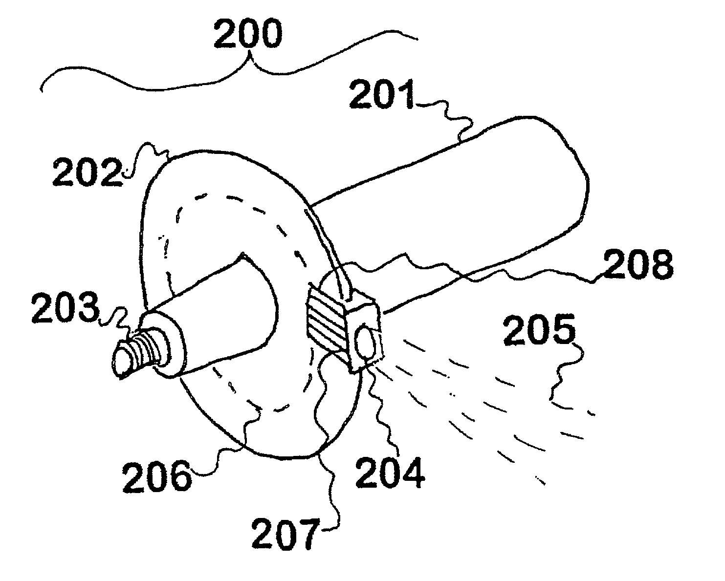
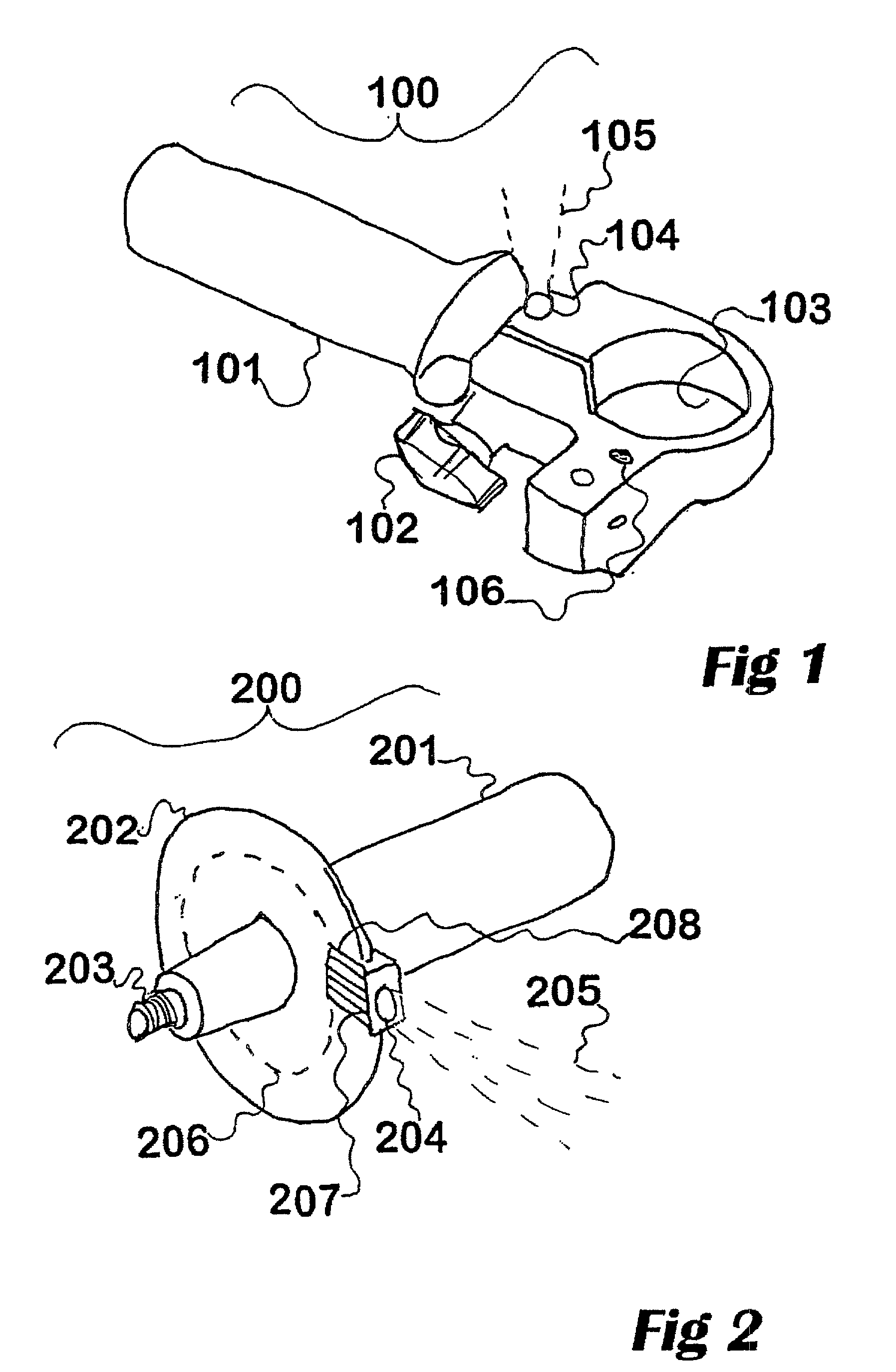
[0067] As seen in FIGS. 1 and 2, an illuminator for a power tool can be constructed to match existing standards for handle attachment. Commonly an electric drill or the like is provided with means for attachment of a handle near the chuck. This helps the operator to hold the tool steady, even if torque results as reaction from the action of the bit against work material. Normally such handles are provided with the ability to be mounted on one side or the other, in case the operator is left-handed or right-handed.
[0068] In FIG. 1, 100 shows a handle modified to be used with a power tool having a collar of certain diameter, which in use is fitted inside the aperture 103 and a clamping screw is tightened with the knob 102 so that the handle is held tight. The actual handle 101 is in this invention made hollow and serves as a battery holder, with a suitable number of (preferably) rechargeable batteries inside. These are connected usually at least with a switch to one or more lamps.
[0069...
example 2
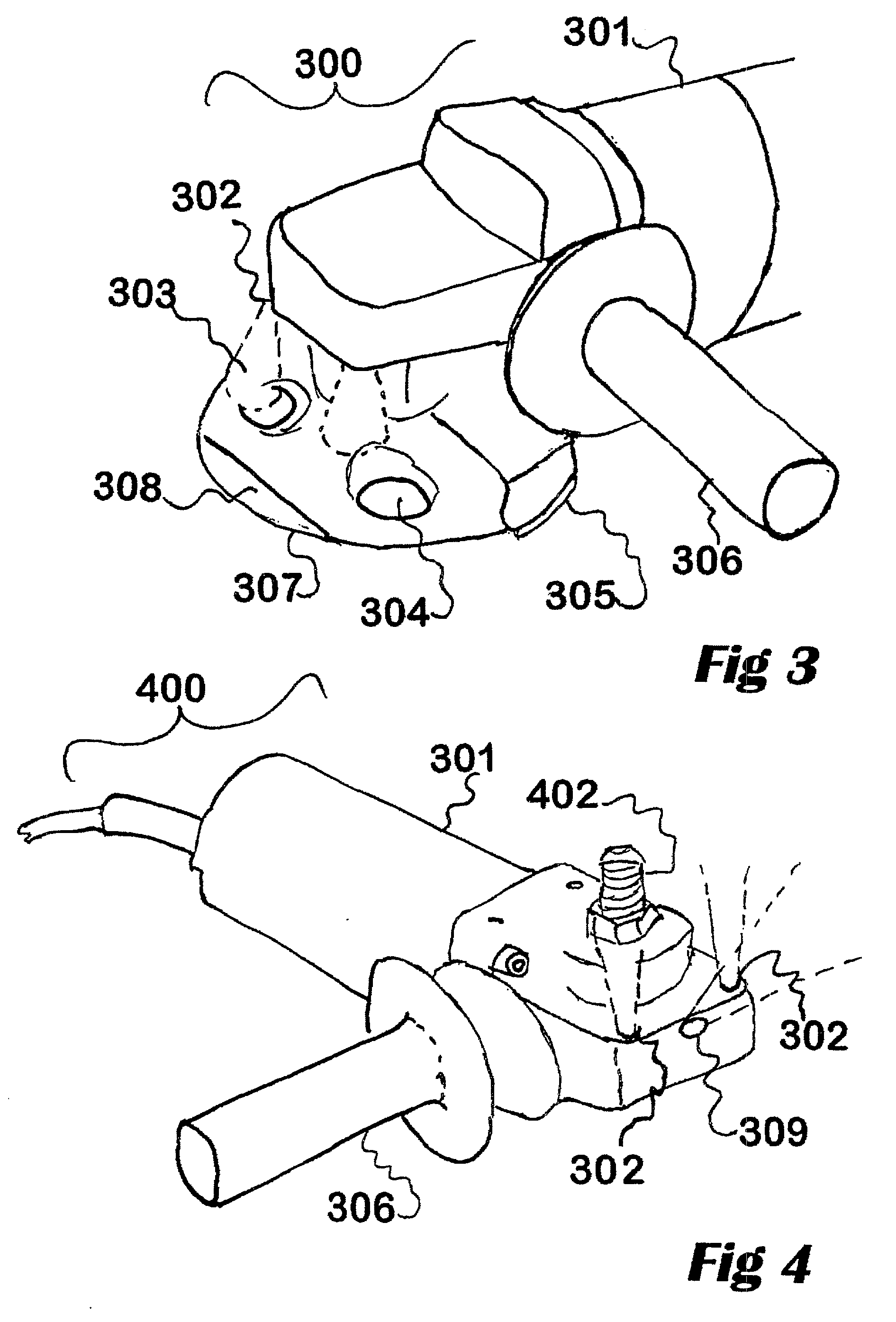
[0073] This example is an illuminator (see FIG. 3) for an angle grinder 301 that can be mounted at the end of the tool (300) nearer the spindle, or built into the tool, the illuminator being capable of emitting light from lamps 302 along paths 303 that are aimed at or through apertures 304 and 308, and thereby form a "transparent" area 307 that is provided for within certain types of abrasive disk and within certain types of backing plate so that the user can see the area of the work surface that is either about to be abraded, or that is being abraded. These types of disk are the subject of earlier patent applications by the inventor and his assignees. In particular they offer the advantages of (1) visibility of the work area and (2) provide for cooling and dust removal. In FIG. 3, 305 is a guard that protects the operator from some danger. FIG. 4 shows the same device 400 from below; including an illuminator, with the abrasive disk, backing plate, and guard removed. The spindle 402...
example 3
[0078] FIG. 5 shows a handle 500 capable of being used as an accessory or replacement for a hand-held circular saw, including provisions for two kinds of illuminator; here a bank 501 of light-emitting diodes (or the like) is provided for a wide beam 508, for general illumination and also an outlet 502 for an intense beam of light 509 such as from a solid-state laser diode. That outlet 502 may either emit the light generated by a laser diode concealed within the handle and conducted through a fibre optic cable 507, or the outlet may instead be an electrical outlet to a remote diode assembly, which generally needs at least three; preferably four wires for the lamp supply current and also a feedback photodiode signal used to regulate the current through the laser diode. The handle 500 would generally be a self-contained unit, of dimensions similar to those of the plain handle supplied with the circular saw, and in one preferred form at least would include one or more batteries inside t...
PUM
| Property | Measurement | Unit |
|---|---|---|
| Power | aaaaa | aaaaa |
| Flexibility | aaaaa | aaaaa |
Abstract
Description
Claims
Application Information
 - R&D
- Intellectual Property
- Life Sciences
- Materials
- Tech Scout
- Unparalleled Data Quality
- Higher Quality Content
- 60% Fewer Hallucinations
Browse by: Latest US Patents, China's latest patents, Technical Efficacy Thesaurus, Application Domain, Technology Topic, Popular Technical Reports.
© 2025 PatSnap. All rights reserved.Legal|Privacy policy|Modern Slavery Act Transparency Statement|Sitemap|About US| Contact US: help@patsnap.com


