
Rotor for rotation sensor

Inactive Publication Date: 2002-10-03
UCHIYAMA MFG
View PDF5 Cites 50 Cited by
  • Summary
  • Abstract
  • Description
  • Claims
  • Application Information

AI Technical Summary

Problems solved by technology

If the pulse generating ring 106 should be damaged, it would not be able to function properly.
Thus, the pulse generating ring 106 would not be able to provide pulses that reflect an accurate number of revolutions.
This presents a fatal defect to the rotation detecting device.

Method used


Image

  • Rotor for rotation sensor
  • Rotor for rotation sensor
  • Rotor for rotation sensor

Examples


first embodiment

[0057] Before proceeding to the detailed description, the preliminary steps are first described. The first step is to prepare a multi-pole magnet. In this step, NBR (acrylonitrile butadiene rubber) is provided, to which a ferrite magnetic powder (strontium ferrite powder) and a rubber chemical are added and mixed together. A rubber, which is still unvulcanized, is thus obtained, which contains 80% by weight of the strontium ferrite powder. Then, the unvulcanized rubber is placed into a mold, where it is vulcanized and shaped into a ring. The ring is then magnetized to provide S poles and N poles such that each S pole and each N pole can appear alternately around its circumference. Finally, the multi-pole magnet 10 is thus obtained.

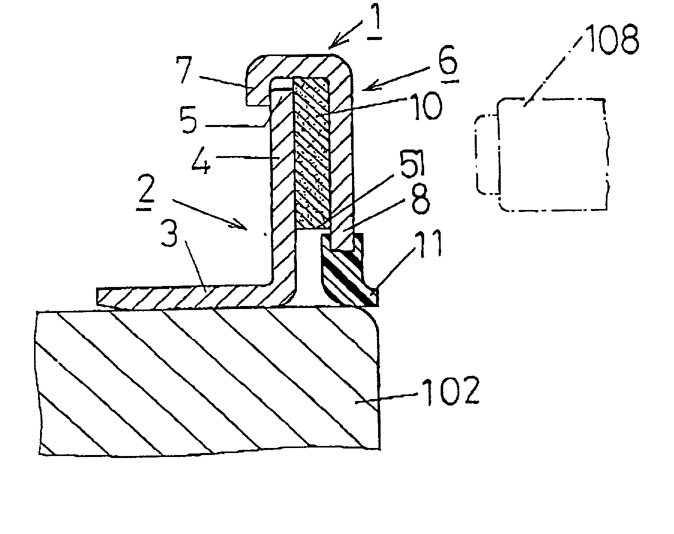
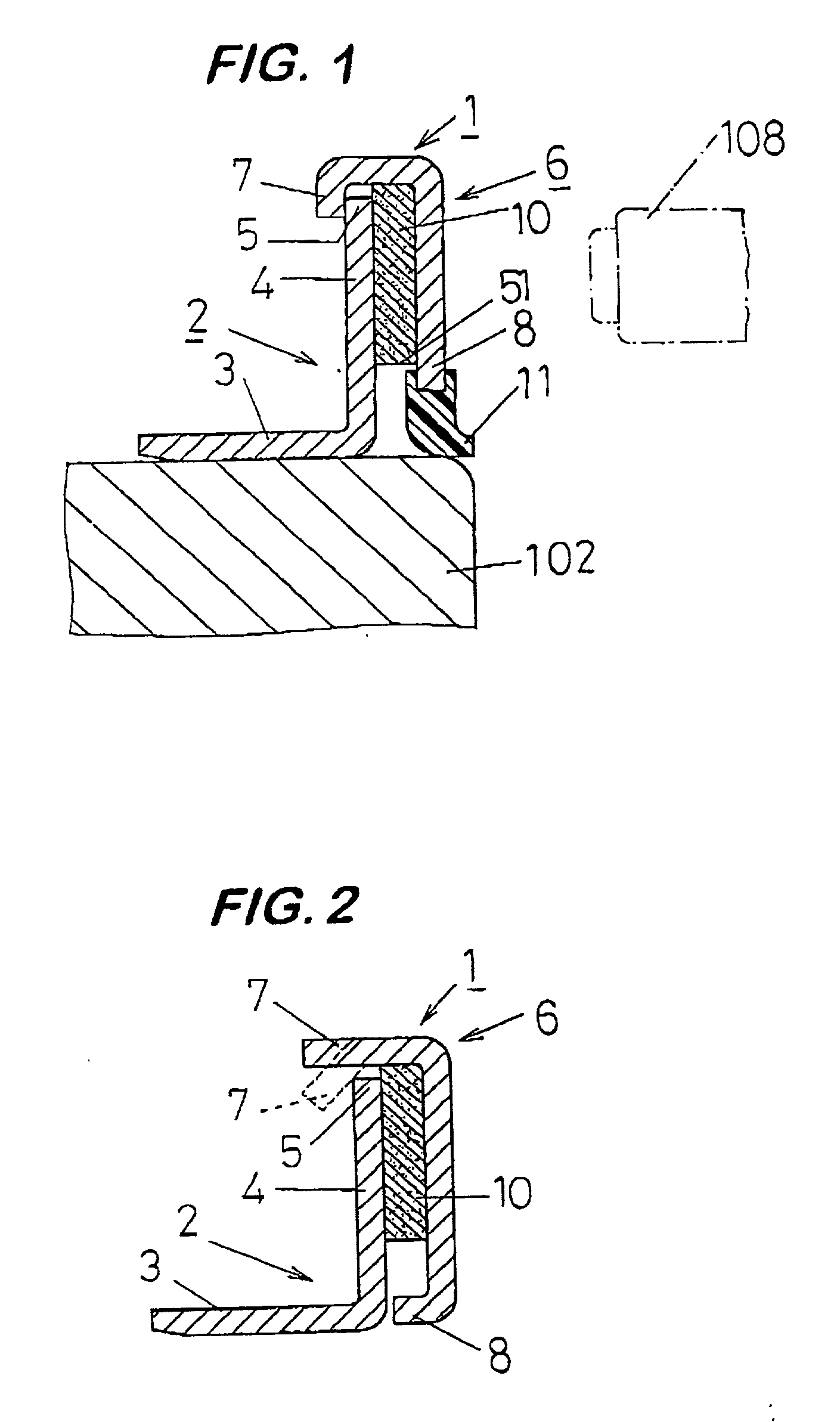
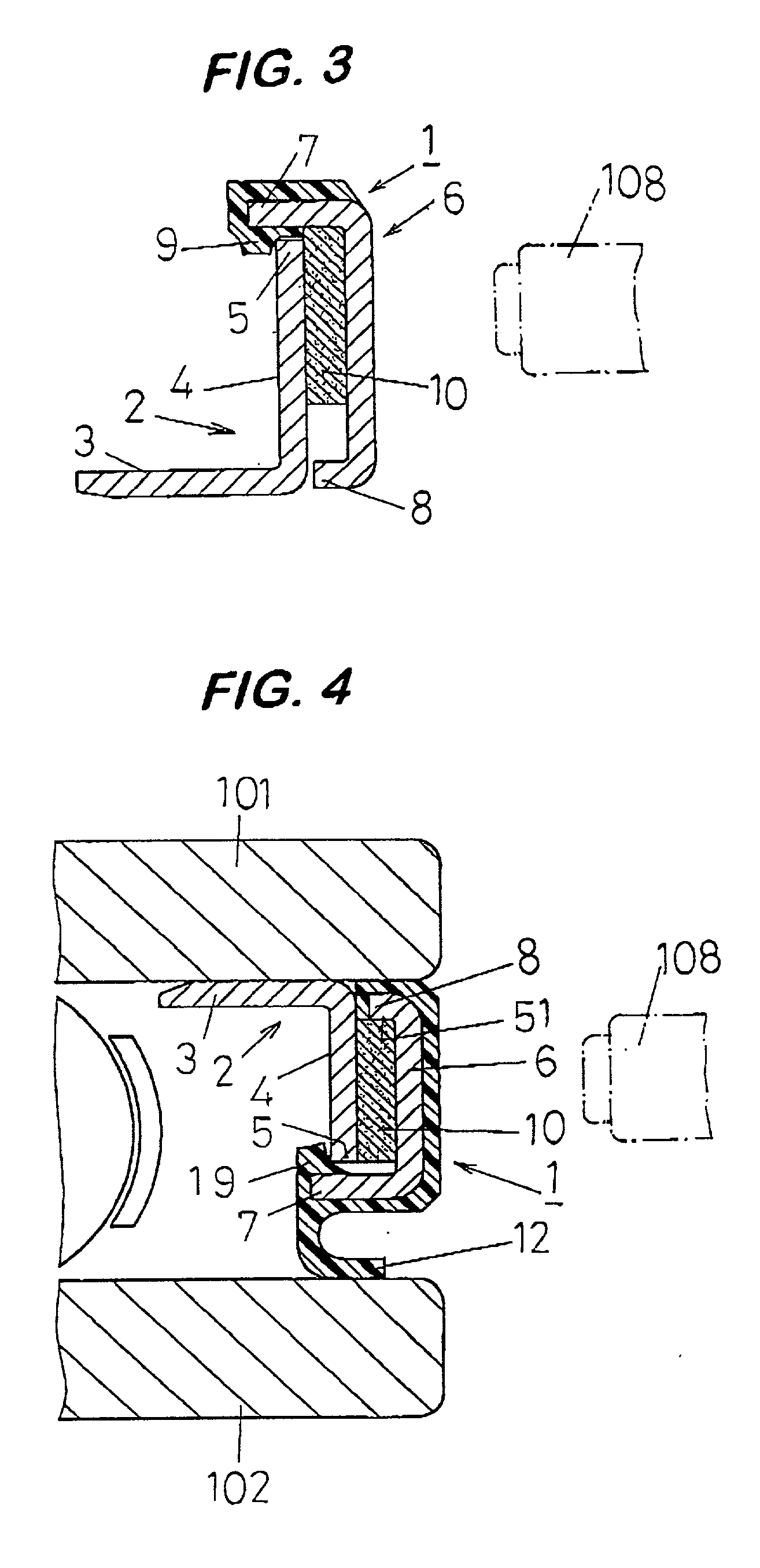
[0058] The second step is to prepare a covering. This covering 6 may be made of an SUS 304 plate of 0.5 mm thick, and includes a synthetic rubber lip 11 that is formed at one end 8 as shown in FIG. 1.

[0059] The third step is to prepare a reinforcing ring. ...

second embodiment

[0063] Before proceeding to the detailed description, the preliminary steps are first described. The first step is to prepare a reinforcing ring. The reinforcing ring 2 is made of metal, and is formed like an L-shape in cross section, including a cylindrical part 3 and a flanged part 4. The flanged part 4 is then processed so that its outer lateral side (the right side in FIG. 12) may have the preliminary base treatment. Following the preliminary base treatment, a coating of an adhesive may then be applied onto the outer lateral side. The second step is to prepare a multi-pole magnet. A rubber material in its unvulcanized state, from which the multi-pole magnet 10 may be formed, is first provided. The rubber material may contain H-NBR hydrogen-added acrylonitrile butadiene rubber), a ferrite magnetic powder (strontium ferrite powder and barium ferrite powder), and a rubber chemical. In this case, the rubber material may preferably contain 85% by weight of the ferrite magnetic powder...


PUM


Abstract

A rotor for the rotation sensor may be mounted on a bearing that supports a wheel on an automotive vehicle so that it can detect the number of revolutions for the wheel. The rotor for the rotation sensor 1 comprises a reinforcing ring 2 formed like an L-shape in cross section, including a cylindrical part 3 adapted to be fitted on the peripheral surface of the rotating part of the bearing (inner race or outer race) and a flanged part 4 bent at the end edge of the cylindrical part 3 from which it extends toward the radial direction, a multi-pole magnet 10 attached to the axial outer lateral side of the flanged part 4, and a non-magnetic covering 6 for enclosing the axial outer lateral side of the multi-pole magnet 10 and having the peripheral edge on its one end secured to the reinforcing ring 2.

Description

[0001] 1. Field of the Invention[0002] The present invention relates generally to a rotation detecting device that may be mounted on the bearing that supports a wheel on an automotive vehicle, and may be used for detecting the number of revolutions for the wheel supported by the bearing and rotating relative to the bearing, and more particularly to a rotor for the rotation sensor that is designed for use on an automotive vehicle on which the anti-lock braking system (ABS) and / or traction control system (TCS) is installed, in order to detect the number of revolutions for each of the front and rear wheels.[0003] 2. Description of the Prior Art[0004] Typically, a conventional rotation detecting device has the following construction. The said rotation detecting device is mounted on each of the wheels on an automotive vehicle for detecting the number of revolutions for each respective wheel, and thereby avoiding that any difference in the revolutions between those wheels occurs. In most ...

Claims


Application Information

Patent Timeline
IPC IPC(8): B60T8/171F16C19/52F16C33/58F16C33/66F16C33/78F16C41/00G01P3/44G01P3/487
CPCF16C33/7869F16C41/007G01P3/487G01P3/443F16J15/326
Inventor ICHIMAN, SHINZABURO
Owner UCHIYAMA MFG
Features
  • Generate Ideas
  • Intellectual Property
  • Life Sciences
  • Materials
  • Tech Scout
  • Unparalleled Data Quality
  • Higher Quality Content
  • 60% Fewer Hallucinations
Learn More